
Method for measuring back vertex power of lens

A technology of back vertex power and measurement method, which is applied in the direction of testing optical performance, etc., can solve the problems of unguaranteed measurement accuracy, huge instrument measuring device, and large space occupation, so as to achieve small instrument occupation space, small instrument measuring device, and measurement Effect of Accuracy Improvement

Active Publication Date: 2014-01-15
NAT INST OF METROLOGY CHINA
View PDF4 Cites 4 Cited by
  • Summary
  • Abstract
  • Description
  • Claims
  • Application Information

AI Technical Summary

Problems solved by technology

[0008] 2) The principle of this measurement is to place the target reticle at a position of 4.6 meters, which makes the instrument measurement device too large and takes up too much space
Measurement accuracy cannot be guaranteed
The linear relationship means that the measurement accuracy corresponding to the moving length of the same reticle is the same, and the non-linear relationship means that the measurement accuracy corresponding to the moving length of the same reticle is different in different positions. In order to ensure the accuracy, more dense The non-linear section of , this will waste a lesser section of the trip

Method used


Image

  • Method for measuring back vertex power of lens
  • Method for measuring back vertex power of lens
  • Method for measuring back vertex power of lens

Examples


Embodiment Construction

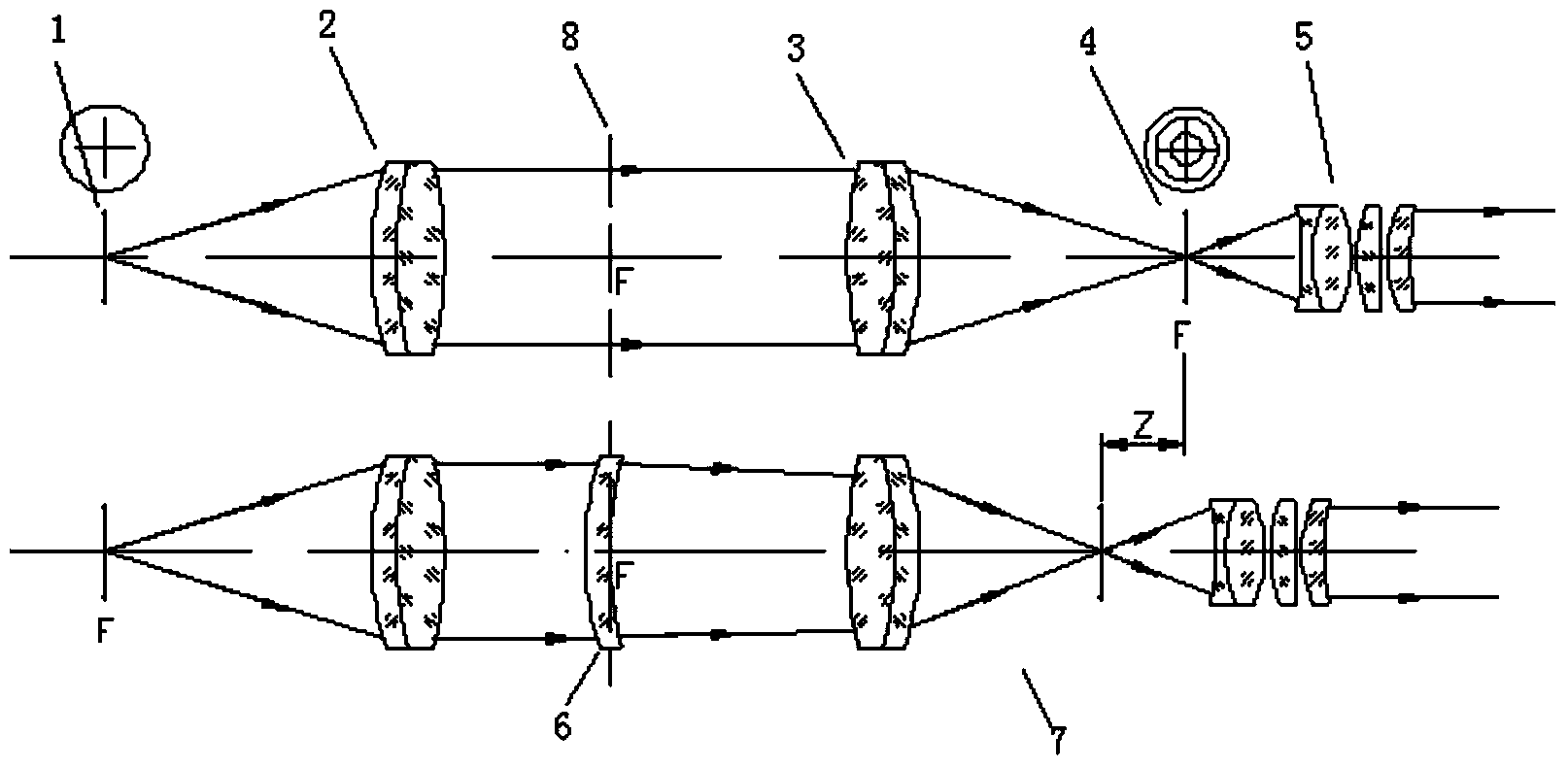
[0029] A kind of measuring method of lens back vertex of the present invention, such as image 3 , including a light source, a target reticle 1, a collimating objective lens 2, and a telescope 7, and also includes the following steps:

[0030] 1) Use the target reticle 1 with the collimating objective lens 2 to produce an infinite target. When the lens 6 under test is not placed in the optical path, the target reticle 1 is located on the focal plane of the collimating objective lens 2, and can be viewed from the telephoto A clear marked image is obtained in the telescopic system composed of the objective lens 3 and the eyepiece 5;

[0031] 2) Place the lens under test 6 between the collimating objective lens 2 and the telescopic objective lens 3;

[0032] 3) Adjust the image square reticle 4, then the image square reticle 4 needs to move a certain distance z along the optical axis in order to obtain a clear image of the target differentiation plate in the telephoto system aga...


PUM


Abstract

The invention provides a method for measuring back vertex power of a lens. A measurement device comprises a light source, a target reticle, a collimator objective and a telescope. An afocal target is generated by means of the collimator objective through the target reticle illuminated by the light source, the to-be-tested lens is arranged between the collimator objective and the telescope, an image space reticle is adjusted so that a clear image of the target reticle is obtained in the telescope, and the back vertex power phi is obtained in a calculating mode through a formula. According to the method, what is measured is the back vertex power in principle, approximation does not exist, the target is arranged to be afocal in the method that the collimator objective is additionally arranged, an instrument measurement device is shortened, integration is achieved, and accordingly an instrument occupies little space, daily maintenance, detection and calibration are facilitated. Due to the fact that the focal length of the telescope is long enough, the measurement accuracy is greatly improved. The vertex power and the moving distance of the image space reticle are in a linear relationship, and accordingly the moving distance is shorter when the same measurement accuracy of the measurement device needs to be reached. The length measurement can be achieved through a mechanical rule, and cost of the instrument is reduced.

Description

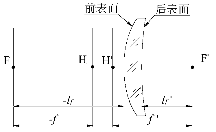
technical field [0001] The invention relates to a method for measuring an optical lens, in particular to a method and a device for measuring the small back vertex of an optical lens. Background technique [0002] The Back vertex power is the reciprocal of the paraxial back vertex of the lens measured in meters. The unit is the reciprocal of the meter (m-1). The distance from the rear vertex of the lens to the paraxial back focus is called the paraxial back focal length, such as figure 1 As shown, where F—object focal point; F′—image focal point; H—object principal point; H′—image principal point; f—object focal length; f′—image focal length; l f — Paraxial front top focal length; l f ′—paraxial back focal length. A lens contains two vertex powers, front and back. According to ophthalmic optics agreement, the vertex power of the lens refers to the back vertex power. [0003] Sunglasses, protective glasses and plano glasses belong to the small vertex power spectacle lens...

Claims


Application Information

Patent Timeline
Patent Type & Authority Applications(China)
IPC IPC(8): G01M11/02
Inventor 李飞刘文丽洪宝玉高明亮朱建平
Owner NAT INST OF METROLOGY CHINA
Learn More