Aiming device and aiming method of X-ray optical system for plasma diagnosis

An optical system and plasma technology, applied in the application of diffraction/refraction/reflection for processing, reducing greenhouse gases, nuclear reactors, etc., can solve the problems of complex system structure, limited aiming accuracy, high manufacturing cost, etc., and achieve high system reliability, The effect of high aiming accuracy and low purchase cost

Inactive Publication Date: 2014-01-15
TONGJI UNIV
View PDF5 Cites 9 Cited by
  • Summary
  • Abstract
  • Description
  • Claims
  • Application Information

AI Technical Summary

Problems solved by technology

This aiming method mainly has the following three disadvantages: 1. The numerical aperture of the X-ray optical system is within 10 -3 -10 -4 At this time, the limit resolution of the visible light diffraction effect reaches hundreds of microns, thus limiting the aiming accuracy; 2. The object image point determined according to the nominal value of the objective lens element parameters deviates from the actual optimal object image point, and The positional relationship between the objective lens element and the object image point of the non-coaxial optical system itself is difficult to accurately calibrate. 3. A set of visible light imaging equipment independent of the X-ray optical system is required, the structure is complex, and additional errors are introduced at the same time, so aiming Less accurate and less reliable
The introduction of telephoto lens, CCD imaging element and post-image processing process can theoretically achieve high aiming accuracy, but the system structure is complicated, the long-term reliability is poor, and the manufacturing cost is high, so it is not suitable for large-scale use in strong laser devices
In the comprehensive physical experiments of future strong laser devices, it will be difficult to have enough space angles to place several to dozens of sets of diagnostic equipment using this aiming mechanism
In addition, this method must directly observe the diagnostic substance, so it is not suitable for the aiming of some black cavity target physical experiments
[0012] The above aiming methods have gradually failed to meet the development requirements of precision plasma diagnostic research, so there is an urgent need for a convenient, flexible and reliable high-precision aiming device and corresponding aiming method for X-ray diagnostic equipment

Method used


Image

  • Aiming device and aiming method of X-ray optical system for plasma diagnosis
  • Aiming device and aiming method of X-ray optical system for plasma diagnosis
  • Aiming device and aiming method of X-ray optical system for plasma diagnosis

Examples


Embodiment 1

[0038] Taking the system assembly and aiming of an 8keV energy point KB type X-ray imaging system as an example to further illustrate the content of the present invention.

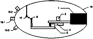
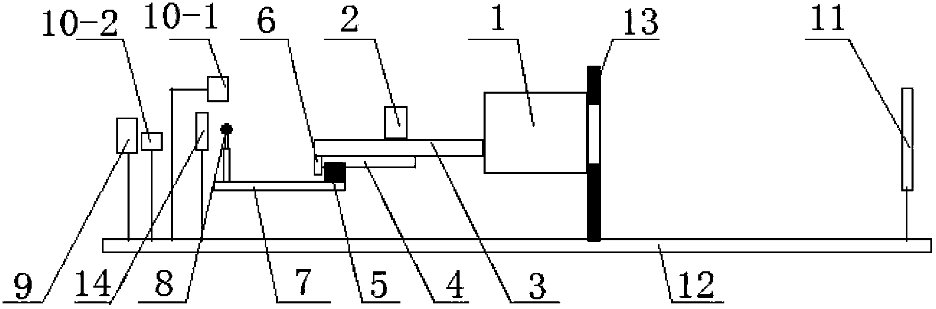
[0039] The aiming method of the KB type X-ray imaging system in the present embodiment is to carry out according to the following steps, as figure 1 As shown, all steps are completed on the optical bench 12. The flange 13 is fixed on the optical platform 12, and is used to simulate the actual working target port of the KB microscope on the strong laser device, and the dimensions are exactly the same. The adjustment mechanism 1 adopts a three-dimensional manual translation platform produced by Beijing Optical Instrument Factory, and is fixed on the flange 13 . Objective lens group 2 adopts W / B working at 8keV energy point 4C multilayer film KB objective lens group. Linear guide rail 4 and slide block 5 are MGN15C linear guide rail and slide block produced by HIWIN Company. The simulated positioning part...

Embodiment 2

[0053] An aiming device of an X-ray optical system for plasma diagnosis, the structure of which is as follows figure 1 As shown, the device includes an analog positioning assembly and its adjustment mechanism 1. The analog positioning assembly includes a positioning rod 7, an analog positioning member 8, a slider 5, a bracket 3, a linear guide rail 4 and an objective lens group 2, and one end of the positioning rod 7 is connected to the analog The positioning part 8 is connected to the slider 5 at the other end, the linear guide rail 4 is provided on the lower side of the bracket 3, and the objective lens group 2 is provided on the upper side, the slider 5 is slidingly connected to the linear guide rail 4, and the bracket 3 is connected to the adjustment mechanism 1. The adjustment mechanism 1 completes the aiming and pointing operations of the X-ray imaging system by adjusting the posture of the X-ray imaging system itself. In addition, according to specific physical experime...


PUM


Abstract

The invention relates to an aiming device and an aiming method of an X-ray optical system for plasma diagnosis. The device comprises an analog positioning assembly and an adjustment mechanism thereof. The analog positioning assembly comprises a positioning rod, an analog positioning member, a slider, a bracket, a linear guide rail and an objective lens group, wherein one end of the positioning rod is connected with the analog positioning member and the other end of the positioning rod is connected with the slider, the lower side of the bracket is provided with the linear guide rail and the upper side of the bracket is provided with the objective lens group, the slider is slidingly connected with the linear guide rail, and the bracket is connected with the adjustment mechanism. The method comprises the following steps: first, coincidence of the analog positioning member and a marking hole of a square-hole mesh is finished under surveillance of a tool microscope; then, an optimal object point of the system and an optimal field of view of the square-hole mesh are enabled to coincide with each other through an X-ray grid imaging experiment; and finally, the objective lens group and the bracket are solidified together by epoxy resin. Compared with the prior art, the collimation device and the collimation method have the advantages of high system reliability, high theoretical and practical aiming accuracy, simple structure, low cost and the like.

Description

technical field [0001] The invention relates to the field of assembly and adjustment of an X-ray optical system for plasma diagnosis, in particular to an aiming device and an aiming method for an X-ray optical system for plasma diagnosis. Background technique [0002] The X-ray optical system is the key equipment for precise plasma diagnosis in the research of inertial confinement fusion (ICF), mainly referring to the KB / KBA and Wolter microscopic imaging systems based on the principle of X-ray grazing incidence reflective imaging, and can also be used in It is used as a light-gathering element in energy spectrum diagnosis to improve the collection efficiency of X-rays. The image quality of this type of optical system changes significantly with the grazing incidence angle, and the effective object field of view is only a few hundred microns. Therefore, the aiming accuracy of the object point must reach tens of microns to achieve high spatial resolution imaging indicators. ...

Claims


Application Information

Patent Timeline
Patent Type & Authority Applications(China)
IPC IPC(8): G21B1/23G21K1/06
CPCY02E30/10
Inventor 穆宝忠伊圣振王占山
Owner TONGJI UNIV
Why Eureka
Try Eureka