
Single-phase inverter and waveform control method thereof

A single-phase inverter, single-phase full-bridge technology, applied in the direction of converting AC power input to DC power output, output power conversion devices, electrical components, etc., can solve the impact of output voltage waveform, component damage, adjustment effect confusion, etc.

Inactive Publication Date: 2014-01-15
HARBIN ENG UNIV
View PDF2 Cites 24 Cited by
  • Summary
  • Abstract
  • Description
  • Claims
  • Application Information

AI Technical Summary

Problems solved by technology

Due to the periodic turn-on and turn-off of diodes, the topology of the entire circuit changes periodically, making the output current of the inverter distorted into a series of peak narrow pulses. Due to the output impedance of the inverter If it is not zero and has a large value near the resonant frequency, the load current will form a voltage drop on the output impedance, and its harmonic components will cause waveform distortion of the voltage at the output terminal of the power supply. The voltage THD value will exceed 5%, and in severe cases it will reach More than 10%, far exceeding the power supply quality standard, and at the same time, it will also affect other electrical equipment connected to the inverter power supply system. In severe cases, it will cause vibration in the circuit and cause damage to components
For the voltage source inverter system, the dead zone delay set to prevent the bridge arm from passing through will also affect the output voltage waveform
[0003] In order to solve the distortion of the output waveform of the inverter power supply, the harmonics of the output voltage can be reduced by the closed-loop control method. The existing control methods include: repetitive control, PI control, state feedback control, sliding mode control, deadbeat control, etc.; single There are various deficiencies in the control of the system. In order to solve the shortcomings of the single control method, compound control can be used. At present, the most commonly used compound control is PI double closed-loop + repetitive control. However, in the paper "PV system grid-connected technology based on voltage control mode "It is mentioned that this compound control scheme can not effectively utilize the ability of the instantaneous value regulator, and the dynamic response is still unsatisfactory. Error, two regulators adjust the same error, and the result is that the two adjustments interfere with each other
Since there is no perfect overall design method for composite controllers, and the two controllers are independently designed, they cannot accurately consider the influence of each other's introduction on the original control model, so the performance of the system cannot be guaranteed; From another point of view, the effect of only using the repetitive controller is to make the output completely track the reference, and there is no phase difference between the output voltage and the reference command, but when only the PID regulator is used, the system output and reference usually have a phase difference. The adjustment characteristics of the two are different. If they are directly combined forcibly, it may cause confusion in the adjustment effect
Due to the existence of the above two factors, in order to ensure the stability of the system and the steady-state output index, the P and I parameters are usually taken to be small, but this directly sacrifices the dynamic response capability of the instantaneous value regulator, and in the end it often fails to achieve The original intention of introducing instantaneous value control

Method used


Image

  • Single-phase inverter and waveform control method thereof
  • Single-phase inverter and waveform control method thereof
  • Single-phase inverter and waveform control method thereof

Examples


Embodiment Construction

[0024] Below in conjunction with accompanying drawing, the present invention is described in more detail:

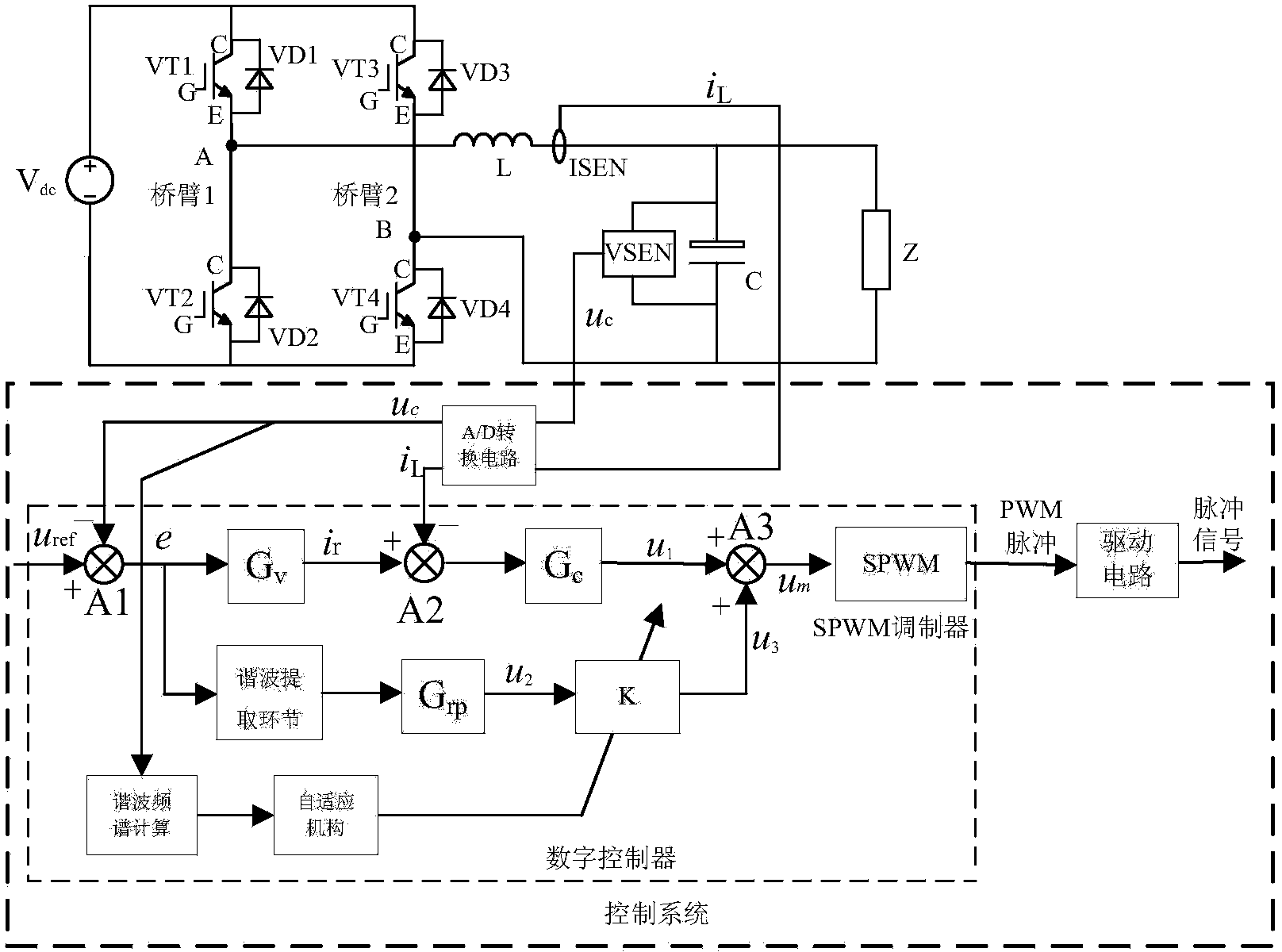
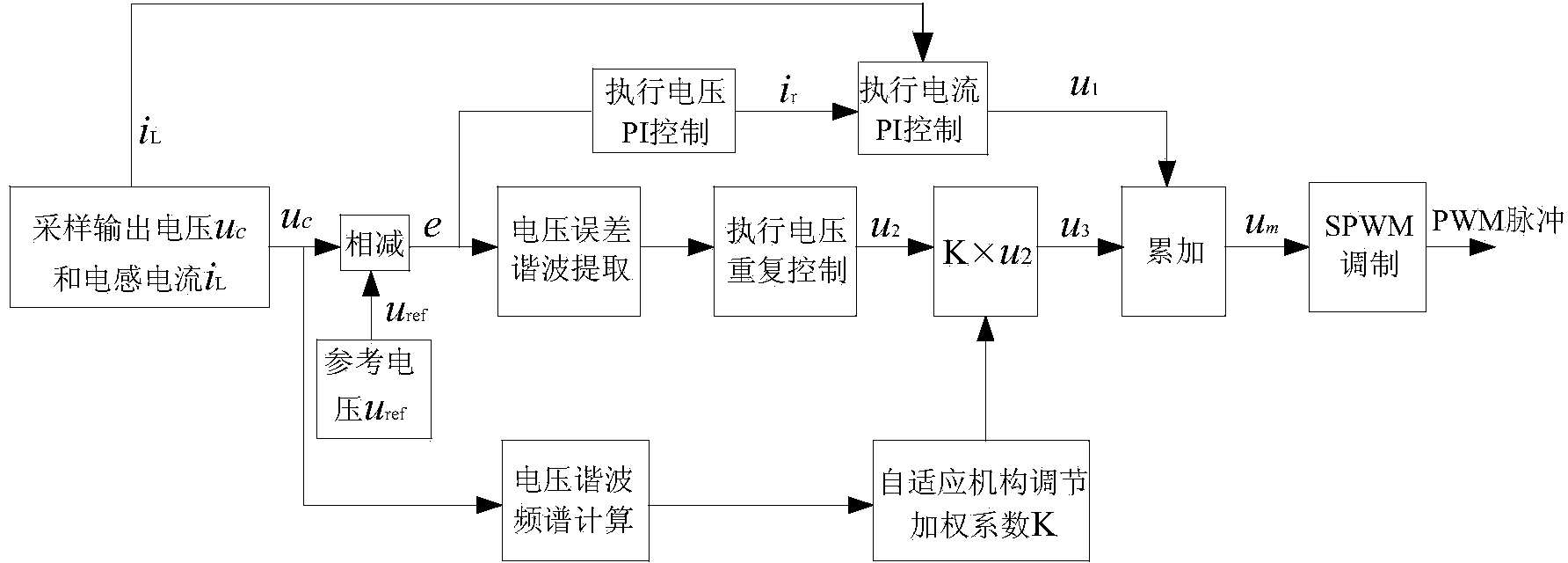
[0025] The present invention proposes a separate control method in inverter power waveform control, using a repetitive controller and a PI controller to independently adjust the harmonics and fundamental waves of the inverter output voltage, and adopting self-adaptive control in the control system Set the output voltage harmonic content detection module to continuously detect the harmonics of the output voltage, carry out real-time weighted control on the output of the repetitive controller according to the harmonic content, and give full play to the respective characteristics of the repetitive controller and the PI controller. The inverter power supply system has a control method with good dynamic and static performance.

[0026] as attached figure 1 As shown, the main circuit of the single-phase inverter includes the input DC power V dc , V dc It can be understood a...


PUM


Abstract

The invention relates to the technical field of electric power and electronics, and in particular relates to a single-phase inverter and a waveform control method thereof. The single-phase inverter comprises an input direct current power supply Vdc, a single-phase full bridge inverter circuit which is composed of 4 power switch tubes and 4 freewheeling diodes which are in antiparallel connection with 4 power switch tubes, a filter inductor L, a filter capacitor C, a load Z, a voltage sensor VSEN, a current sensor ISEN, an A / D conversion circuit, a digital controller and a driver circuit. According to the invention, when the harmonic content is large, the parameter K of an adjustable system is adjusted, so that a repetitive controller plays the main role and the system is stable; when the harmonic content is small, the parameter K of the adjustable system is adjusted, so that a PI controller plays the main role and the system has fast response speed; and the control scheme integrates the characteristics of repetitive control and PI control and gives full play to the advantages of compound control, so that the system has the advantages of good output waveform, fast dynamic response, strong adaptability to the load and the like.

Description

technical field [0001] The invention relates to the technical field of power electronics, in particular to a single-phase inverter and a waveform control method thereof. Background technique [0002] Among various power electronic devices, the inverter has the widest application range, but the application field of the inverter faces many nonlinear problems, which affects the quality of the output voltage waveform of the inverter. Among these non-linear factors, the rectifying load occupies a considerable proportion. Due to the periodic turn-on and turn-off of diodes, the topology of the entire circuit changes periodically, making the output current of the inverter distorted into a series of peak narrow pulses. Due to the output impedance of the inverter If it is not zero and has a large value near the resonant frequency, the load current will form a voltage drop on the output impedance, and its harmonic components will cause waveform distortion of the voltage at the output ...

Claims


Application Information

Patent Timeline
Patent Type & Authority Applications(China)
IPC IPC(8): H02M7/5387H02M1/12
Inventor 游江张国千孟繁荣罗耀华巩冰
Owner HARBIN ENG UNIV
Learn More