Downlink communication method in high speed railway system and device thereof

A downlink, high-speed railway technology, applied in wireless communications, multi-frequency code systems, baseband system components and other directions, can solve problems such as increased call drop rate, system performance degradation, and user experience deterioration, and reduce impact. , the effect of improving throughput

Inactive Publication Date: 2014-01-15
POTEVIO INFORMATION TECH CO LTD
View PDF4 Cites 31 Cited by
  • Summary
  • Abstract
  • Description
  • Claims
  • Application Information

AI Technical Summary

Problems solved by technology

[0004] 1. The throughput of the system is far from meeting the needs of current users for data services
[0005] 2. High-speed movement causes the user terminal to stay in the cell for too short a time, resulting in frequent mobile switching of the user terminal, and frequent mobile switching may easily cause signaling storms
[0006] 3. The high-speed movement of the user terminal will cause serious Doppler frequency shift, and the link transmission reliability will be reduced, which will further prolong the mobile switching time of the user terminal
[0007] 4. Frequent mobile switching of user terminals leads to a significant increase in call drop rate, which ultimately leads to poor user experience
[0013] After adopting the above-mentioned high-speed railway broadband communication scheme based on distributed BBU+RRU+train base station, Doppler frequency offset correction becomes a key technology, especially in the overlapping area of ​​two RRUs, the signals sent by different RRUs will generate multiple signals in different directions to the UE. Doppler frequency offset, in this way, after being superimposed on the UE side, it is difficult for the UE to estimate and correct the Doppler frequency offset, resulting in a serious decline in system performance
At present, no corresponding solution has been proposed for the above problems

Method used


Image

  • Downlink communication method in high speed railway system and device thereof
  • Downlink communication method in high speed railway system and device thereof
  • Downlink communication method in high speed railway system and device thereof

Examples


Embodiment Construction

[0026] In order to make the purpose, technical solution and advantages of the present invention clearer, the present invention will be further described in detail below in conjunction with the accompanying drawings and specific embodiments.
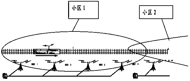
[0027] The core idea of ​​the present invention is: according to the characteristics of the uplink data communication, select the RRU with the best channel condition to transmit the service channel data; Control data is sent on the RRU to meet cell-level coverage of control information. In this way, the problem of poor performance of the frequency offset correction algorithm in the overlapping coverage area of ​​the two RRUs in the high-order modulation mode can be avoided, and the throughput of the system is greatly improved.

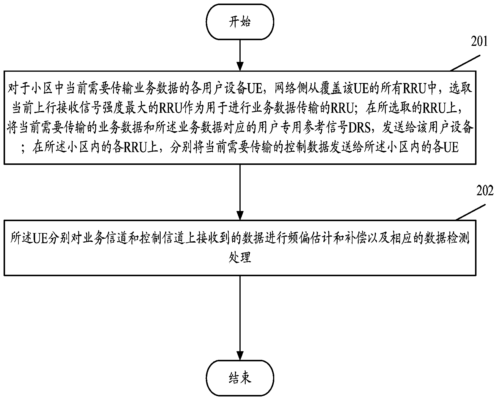
[0028] figure 2 It is a schematic flow chart of the method in Embodiment 1 of the present invention. Such as figure 2 As shown, the method includes the following steps:

[0029] Step 201, for each user equip...


PUM


Abstract

The application discloses a downlink communication method in a high speed railway system and a device thereof. The method comprises the following steps: a, as for each user equipment UE and network side which need to transmit business data at present in a cell, a RRU with the highest current uplink received signal strength is selected as the RRU used for business data transmission from all RRUs covering the UE; on the selected RRU, the business data which needs to be transmitted currently and a user dedicated reference signal DRS corresponding to the business data are sent to the user equipment; and on each RRU in the cell, control data which needs to be transmitted currently is respectively sent to each UE in the cell; and b, the UE respectively carries out frequency offset estimation and compensation and corresponding data detection processing on data received on a traffic channel and a control channel. By the method provided by the invention, the influence of Doppler frequency offset on distributed high speed railway system performance can be reduced effectively.

Description

technical field [0001] The present application relates to mobile communication technology, in particular to a downlink communication method and device in a high-speed railway system. Background technique [0002] The existing railway communication scheme generally adopts the GSM-R system. GSM-R draws on the technology of the public network GSM cellular system, and retains the general structure of GSM. Both can work in the 900MHz frequency band, and the interval between two adjacent channels is 200kHz. Each channel adopts time division multiple access. Divided into 8 time slots. Frequency reuse is used to avoid interference between channels in the same channel and adjacent areas. It is also basically the same in terms of wireless network planning; the dispatching communication function and elements suitable for use in high-speed environments have been added. A typical GSM-R network installs directional antennas along the track to form an elliptical cell along the track. Th...

Claims


Application Information

Patent Timeline
Patent Type & Authority Applications(China)
IPC IPC(8): H04L25/02H04L25/03H04L27/26H04W8/08
Inventor 王绪振冯绍鹏李元柳张际
Owner POTEVIO INFORMATION TECH CO LTD
Why Eureka
Try Eureka