High-voltage capacitive voltage divider

A high-voltage capacitor and capacitor voltage dividing technology, applied in the direction of voltage divider, etc., can solve the problems of high use cost, high price, bulky volume, etc., and achieve the effects of convenient processing, convenient production, and adjustable sampling transformation ratio.

Inactive Publication Date: 2014-01-22
无锡希恩电气有限公司
View PDF10 Cites 3 Cited by
  • Summary
  • Abstract
  • Description
  • Claims
  • Application Information

AI Technical Summary

Problems solved by technology

This type of equipment is usually bulky, complex in structure, expensive and expensive to use

Method used


Image

  • High-voltage capacitive voltage divider

Examples


Embodiment Construction

[0014] Below the present invention will be further described in conjunction with the embodiment in the accompanying drawing:

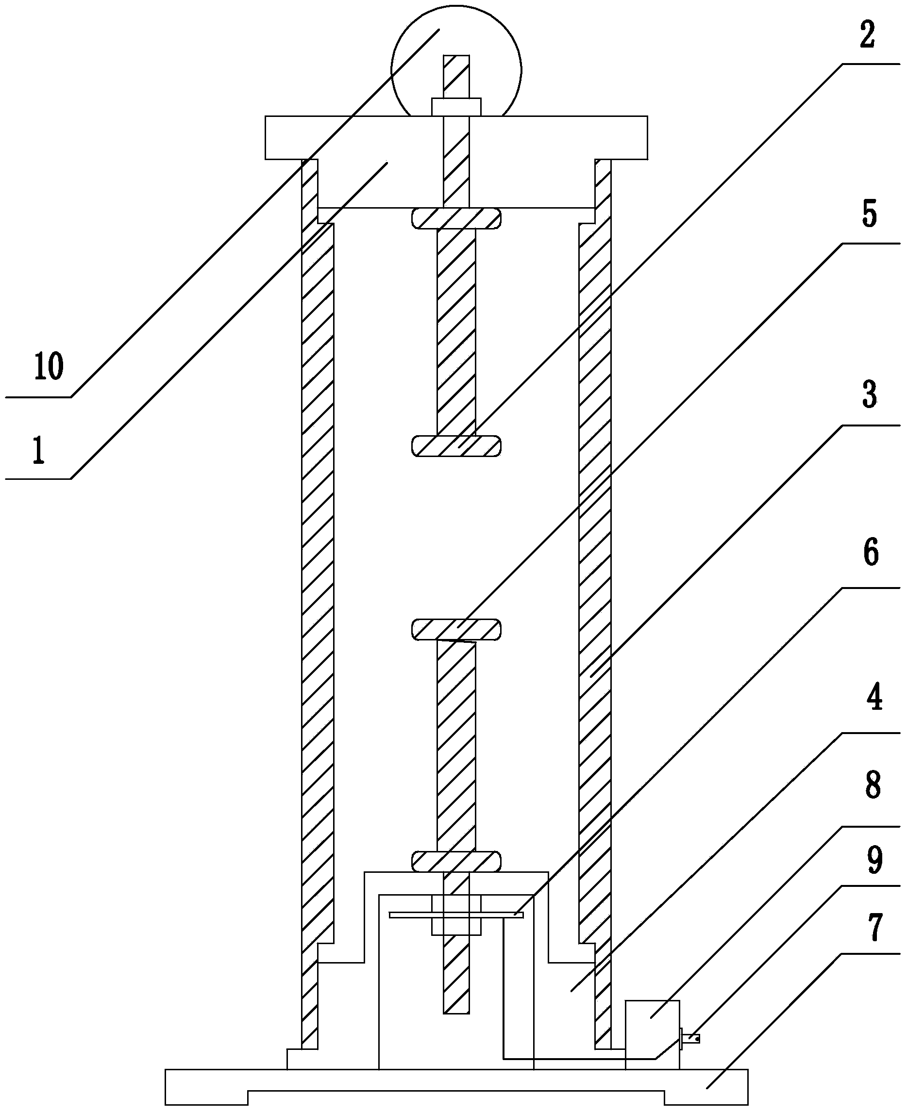
[0015] Such as figure 1 As shown, the present invention mainly includes a high-pressure epoxy barrel 3, and the upper and lower ends of the high-pressure epoxy barrel 3 are sealed and connected to the upper flange 1 and the lower flange 4 respectively.

[0016] The inner surface of the upper flange 1 is provided with a high-voltage pole plate 2 , and the lead-out screw connected to the upper end of the high-voltage pole plate 2 passes through the upper flange 1 and connects with the discharge ball 10 .

[0017] The inner surface of the lower flange 4 is provided with a sampling pole plate 5 , and the lead-out screw rod connected to the lower end of the sampling pole plate 5 passes through the lower flange 4 and connects to the capacitive voltage divider plate 6 .

[0018] The lower end of the lower flange 4 is connected to a base 7, and a socket base ...


PUM


Abstract

The invention relates to a capacitive voltage divider, in particular to a high-voltage capacitive voltage divider used for 150kV, which belongs to the technical field of capacitive voltage dividers. The capacitive voltage divider comprises a high-voltage epoxy cylinder, wherein an upper flange and a lower flange are respectively hermetically connected to the upper end and the lower end of the high-voltage epoxy cylinder, a high-voltage polar plate is arranged on the inner side surface of the upper flange, and a led-out screw rod which is connected to the upper end of the high-voltage polar plate penetrates through the upper flange and is connected with a discharging ball. A sampling polar plate is arranged on the inner side surface of the lower flange, and a led-out screw rod which is connected to the lower end of the sampling polar plate penetrates through the lower flange and is connected with a capacitive voltage dividing plate. The lower end of the lower flange is connected with the base, a socket base is arranged on the base, and a socket is fixedly arranged on the socket base. The high-voltage capacitive voltage divider adopting the high-voltage epoxy cylinder as the cylinder has the advantages of seal property, little possibility of deforming, high voltage resistance, convenience in processing and cost saving. Due to the adoption of an oil immersion type structure, the voltage resistance can be improved, and the size can be reduced. The high-voltage capacitive voltage divider can measure high voltage which is lower than 150KV, the sampling non-load voltage ratio is adjustable, and the feasibility is strong.

Description

technical field [0001] The invention relates to a capacitor voltage divider, specifically a high-voltage capacitor voltage divider for 150kV, and belongs to the technical field of capacitor voltage dividers. Background technique [0002] At present, high-voltage transformers with oil tank structures are widely used. In order to measure the high-voltage output data of the high-voltage transformer when it is working, high-voltage testing equipment is used. This type of equipment is usually bulky, complex in structure, expensive and expensive to use. Contents of the invention [0003] The purpose of the present invention is to overcome the above disadvantages, so as to provide a high-voltage capacitive voltage divider, which has small volume, good pressure resistance performance, can accurately measure high-voltage voltage not higher than 150KV, and can customize the transformation ratio according to user needs. [0004] According to the technical solution provided by the p...

Claims


Application Information

Patent Timeline
Patent Type & Authority Applications(China)
IPC IPC(8): G01R15/06
Inventor 钱明徐惠丰周晓东
Owner 无锡希恩电气有限公司
Why Eureka
Try Eureka