
Substrate transfer facility and transfer method

A technology of transportation equipment and transportation method, which is applied in the direction of transportation and packaging, conveyor objects, electrical components, etc., which can solve the problems of increasing the overall operating cost and increasing cycle time, so as to reduce the amount of handling, reduce the production cycle time, and increase production capacity Effect

Active Publication Date: 2014-01-22
SHENZHEN CHINA STAR OPTOELECTRONICS TECH CO LTD
View PDF4 Cites 0 Cited by
  • Summary
  • Abstract
  • Description
  • Claims
  • Application Information

AI Technical Summary

Problems solved by technology

[0004] The object of the present invention is to provide a substrate transportation equipment and transportation method to overcome the above-mentioned problems in view of the defects that the existing substrate method will increase the overall operating cost and increase the cycle time

Method used


Image

  • Substrate transfer facility and transfer method
  • Substrate transfer facility and transfer method
  • Substrate transfer facility and transfer method

Examples


Embodiment Construction

[0027] The present invention will be described in detail below in conjunction with the accompanying drawings and specific embodiments.

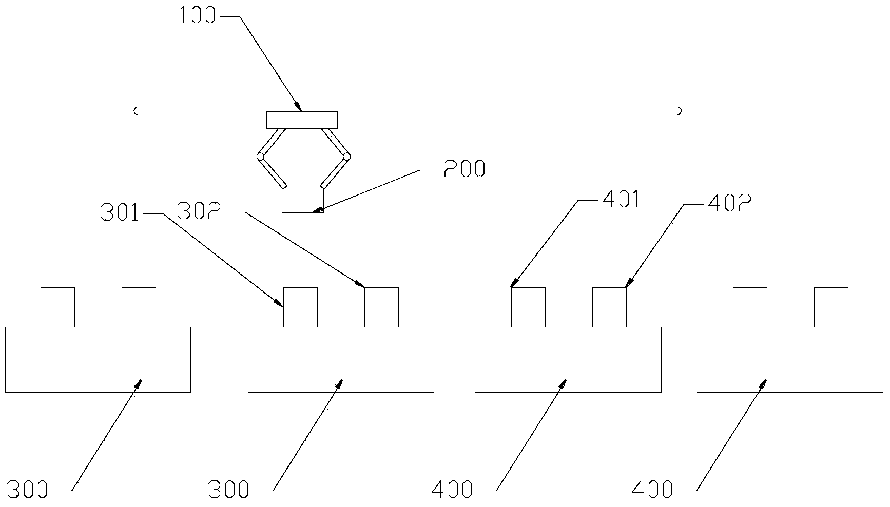
[0028] In order to overcome such as figure 1 In the prior art, the handling machine 100 needs to carry the cassette 200 multiple times during the substrate production process. The present invention improves the original way of setting the processing chambers in parallel, so that the number of times the cassette 200 is transported by the transporter 100 is minimized during the transport process.

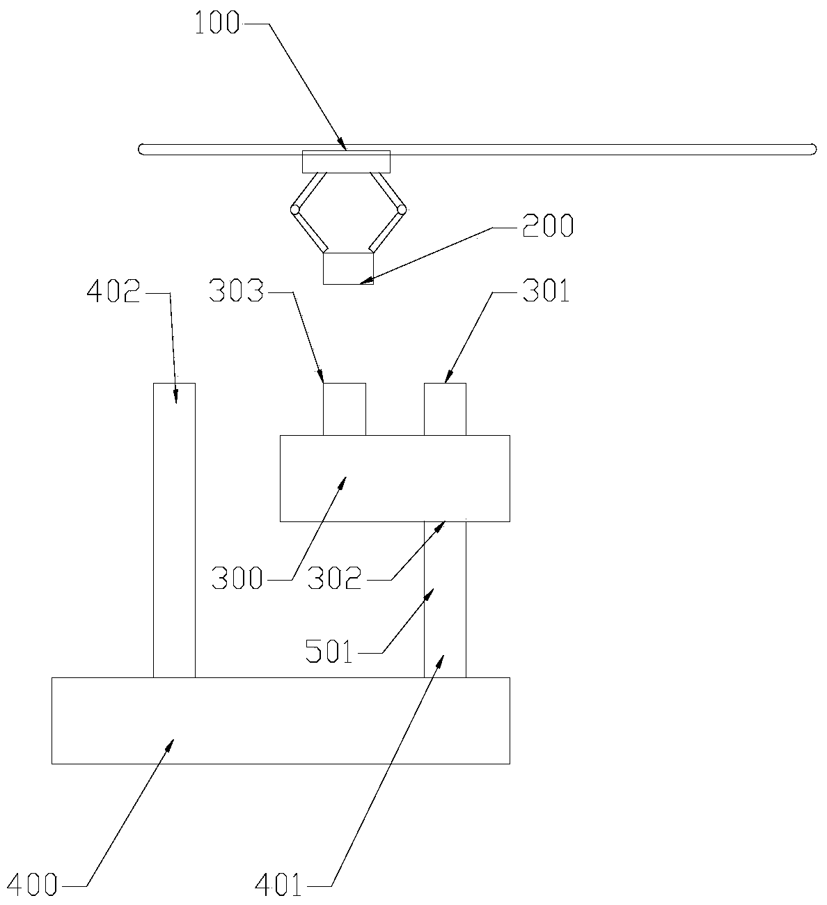
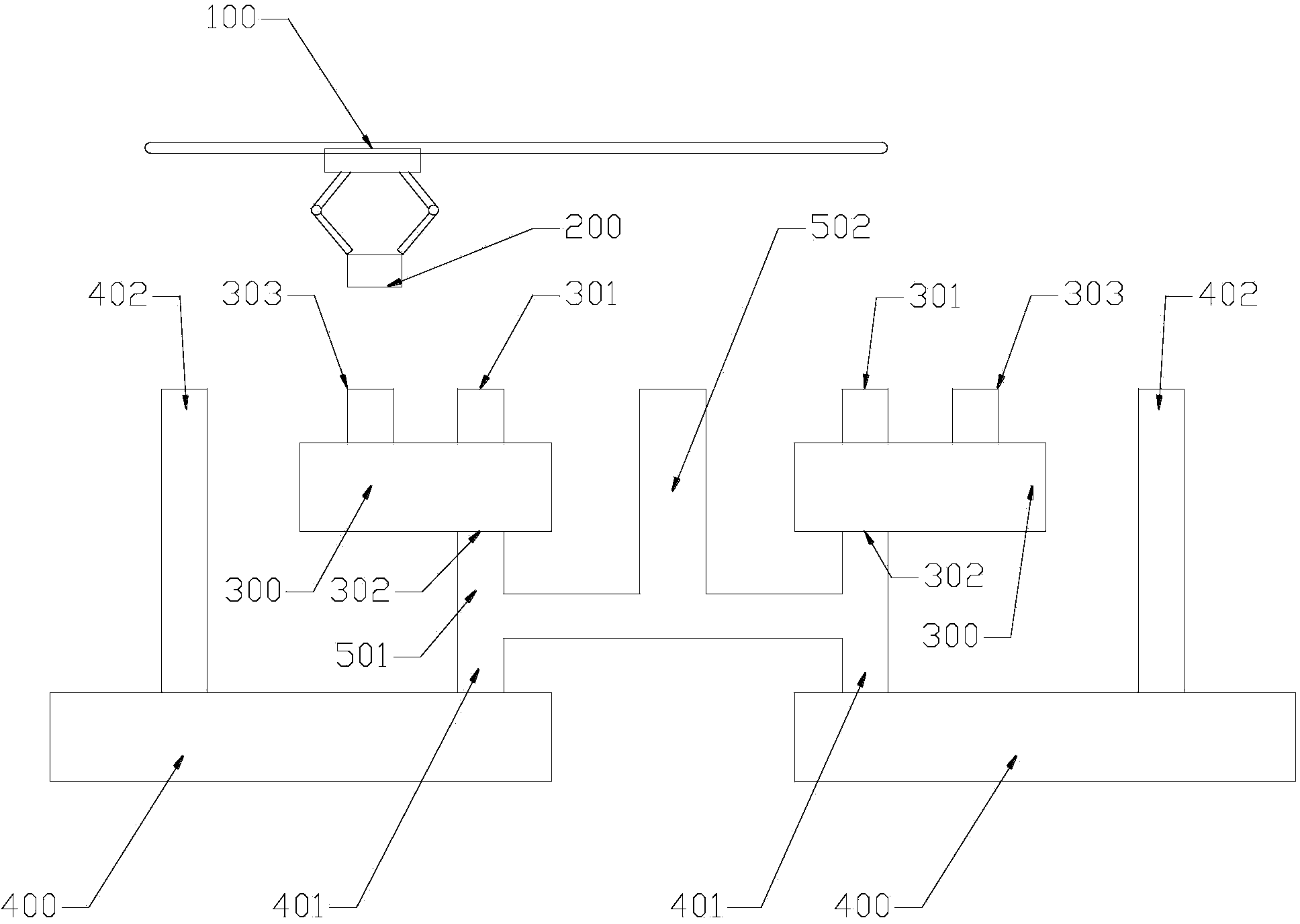
[0029] Such as figure 2 Shown is a schematic structural view of the first embodiment of the substrate transportation equipment of the present invention. In this embodiment, the original processing chambers arranged in parallel are changed to a mixed series form, that is, the first processing chamber 300 and the second processing chamber 400 are opposite to each other. The moving direction of the conveyor 100 is vertically arranged, the first proce...


PUM


Abstract

The invention relates to a substrate transfer facility and a transfer method, wherein the facility comprises a cartridge for loading substrates and a transfer machine for transferring the cartridge, and a first processing chamber and a second processing chamber which are used for processing the cartridge are sequentially arranged along a direction perpendicular to the moving direction of the transfer machine; and the substrate transfer facility also comprises a first conveyer belt which is arranged between the first processing chamber and the second processing chamber and used for driving the cartridge to move from the first processing chamber to the second processing chamber. By implementing the invention, the technical processes of the first processing chamber and the second processing chamber can be fulfilled as long as the transfer machine transfers the cartridge to an inlet without intermediate processing, consequently, the transfer load of the transfer machine is reduced, the substrate production cycle is shortened, and productivity is increased.

Description

technical field [0001] The present invention relates to substrate technology, and more specifically, to a substrate transportation device and transportation method. Background technique [0002] In the process of substrates, such as TFT-LCD substrates, different processes need to be processed in different processing chambers, such as coating, exposure, etching, photoresist removal, etc., all need to be processed in different processing chambers. At present, the industry adopts the following methods for the handling of substrates between processing chambers: figure 1 The way. Each processing chamber is set parallel to the moving direction of the transporter. After the substrates to be processed are loaded by the cassette 200, they are transported to the first entrance 301 of the first processing chamber 300 by the transporter 100 (crane). A processing chamber 300 is processed, and the processed cassette 200 is output from the first outlet 302 of the first processing chamber...

Claims


Application Information

Patent Timeline
Patent Type & Authority Applications(China)
IPC IPC(8): H01L21/677
CPCH01L21/67736H01L21/6773H01L21/67733H01L21/67739
Inventor 陈增宏吴俊豪林昆贤汪永强杨卫兵齐明虎李晨阳子杨国坤蒋运芍舒志优
Owner SHENZHEN CHINA STAR OPTOELECTRONICS TECH CO LTD
Learn More