Cyclic time to digital convertor

A digital converter and cycle time technology, applied in analog/digital conversion, code conversion, instrumentation, etc., can solve the problems of high delay unit matching requirements, multi-chip area, consumption, etc.

Active Publication Date: 2014-01-22
天津海芯光电科技有限公司
View PDF5 Cites 7 Cited by
  • Summary
  • Abstract
  • Description
  • Claims
  • Application Information

AI Technical Summary

Problems solved by technology

In addition, the TDC of the delay line or the time reduction structure requires a large number of delay units, which not only consumes too much chip area, bu

Method used


Image

  • Cyclic time to digital convertor
  • Cyclic time to digital convertor
  • Cyclic time to digital convertor

Examples


Embodiment Construction

[0030] In order to increase the input range of the traditional TDC, maintain linearity within a larger input range and reduce design requirements. The present invention provides a cycle time digital converter circuit, which is described in detail below:

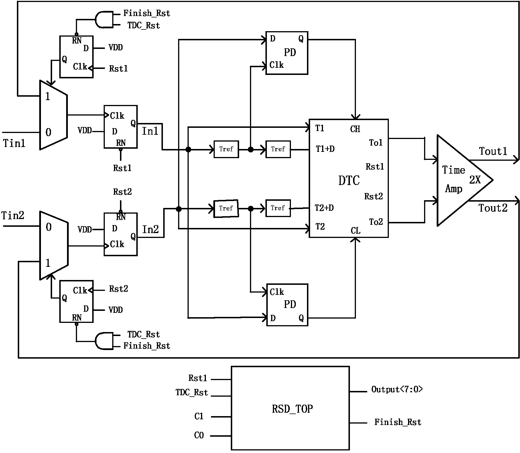
[0031] See figure 1 , The circuit block diagram of the cycle time digital converter includes: multiplexer, D flip-flop, delay unit, phase detector, sub-DTC (digital to time converter), readout circuit, time amplifier, NOT gate, AND gate Wait.

[0032] Cyclic TDC adopts a symmetrical structure. The symmetrical structure can obtain an algorithm similar to Cyclic ADC and eliminate matching errors to obtain good linearity. The multiplexer selects the initial time signal and the residual signal. The PD phase detector compares the phase difference between In1 and In1 after passing through the delay unit. The result of the comparison is used as the DTC input for further conversion.

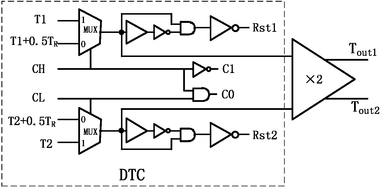
[0033] The principle circuit diagram of DTC see ima...


PUM


Abstract

The invention relates to the field of analog integrated circuit design of microelectronics, and provides a cyclic time to digital convertor (Cyclic TDC) in order to further expand an input range of the traditional TDC, allow the TDC to maintain the linear characteristic in a larger input range, and reduce a design matching requirement. The cyclic TDC adopts the technical scheme that a difference value of two input time signals is converted into corresponding digital codes by a sub TDC; a time margin obtained by conversion of the sub TDC is amplified by a time 2* magnifier; the amplified time margin enters the sub TDC for quantization through a multiplexer; a cyclic conversion process is performed to the required precision; the converted digital codes are subjected to dislocation addition by a reading circuit; and the obtained final digital code is output by the reading circuit, so that the conversion from the time signals to the digital codes is accomplished. The cyclic TDC is mainly applied to the analog integrated circuit design.

Description

Technical field [0001] The invention relates to the field of analog integrated circuit design of microelectronics, in particular to a cycle time digital converter (Cyclic TDC). technical background [0002] Time to digital converters (TDC) are widely used in many applications, such as phase and frequency detection in digital / analog phase-locked loops. In recent research, TDC is applied to ADC based on time domain to realize the conversion of time to digital. The existing TDC types include counter structure, delay line structure, time reduction structure and Vernier structure. [0003] The above technology has at least the following shortcomings and shortcomings: [0004] The input range of traditionally proposed time-to-digital converters is only tens to hundreds of picoseconds, because only within this range can the linear conversion output of the TDC structure be guaranteed. In addition, the TDC of the delay line or the time reduction structure requires a large number of delay u...

Claims


Application Information

Patent Timeline
IPC IPC(8): H03M1/50
Inventor 徐江涛朱昆昆高静史再峰姚素英
Owner 天津海芯光电科技有限公司
Why Eureka
Try Eureka