Roller shaft assembly having air cooling structure and used for crushing machine and air cooling roller shaft type crushing machine

An air-cooled structure and crusher technology, applied in grain processing, etc., can solve problems such as bearing overheating, high product cost, and high operating cost, and achieve the effects of improving surface hardness and wear resistance, improving linear stiffness, and reducing operating costs

Inactive Publication Date: 2014-01-29
富士摩根冷却机(天津)有限公司
View PDF6 Cites 10 Cited by
  • Summary
  • Abstract
  • Description
  • Claims
  • Application Information

AI Technical Summary

Problems solved by technology

When working, each pair of rollers crushes the bulk material to particles with a particle size below 25mm during the rotation process. Since the temperature of the rollers can reach about 450°C when the material temperature is as high as 500-600°C, this is required. The roller sleeve of this type of roller crusher must be resistant to high temperature and wear, so the material selection is very strict. Generally, high-strength alloy materials such as high chromium and high nickel must be used to manufacture roller sleeve castings, and the price is as high as 50,000-60,000 yuan / ton, high manufacturing cost
However, its hardness is about 40HRC, and its wear resistance decreases after high temperature, and it is prone to cracks. Once the wear is serious, it cannot be repaired and can only be replaced with a new one, so the operating cost is also high.
Moreover, working at high temperature will cause the bearing to overheat and cause damage. Moreover, the existing roller sleeve is a solid body, which requires many consumables and high product cost.
[0003] In addition, as mentioned above, there is an expansion gap between the roller sleeve and the limit flange, but because of the rigid connection, under the action of the rotating radial force component, the roller sleeve will move to the shaft end, and the workpiece will be caused by hard contact. damage
In particular, the shaft body also bears the bending force formed by the weight pressure of the roller sleeve, the lateral pressure of the extruded material and its own gravity, which also leads to its easy deformation and damage, which affects the service life

Method used


Image

  • Roller shaft assembly having air cooling structure and used for crushing machine and air cooling roller shaft type crushing machine
  • Roller shaft assembly having air cooling structure and used for crushing machine and air cooling roller shaft type crushing machine
  • Roller shaft assembly having air cooling structure and used for crushing machine and air cooling roller shaft type crushing machine

Examples


Embodiment 1

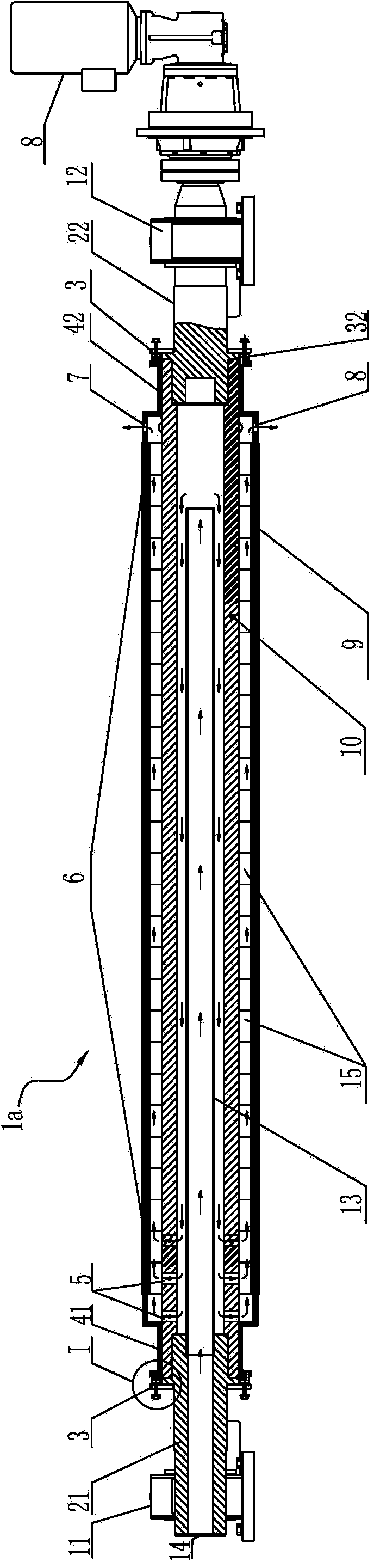
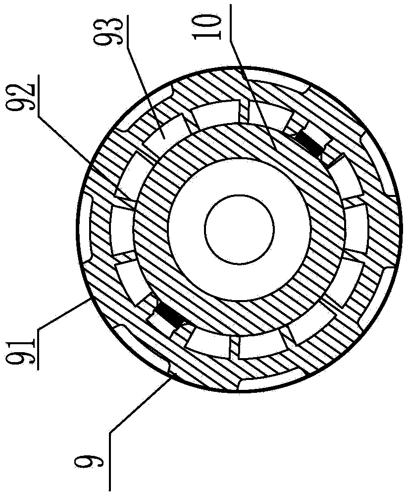
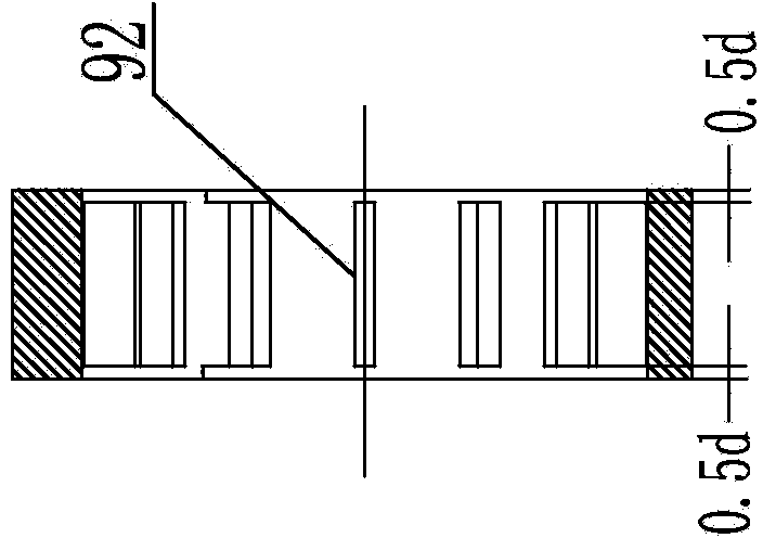
[0028] Figure 1 to Figure 4 It shows a roller shaft assembly 1a for a crusher with an air-cooled structure, including a roller shaft composed of a core tube 10 and a roller sleeve 6 formed of several parallel toothed rollers 9 fixedly fitted thereon One end of the core tube 10 is the driving end and is connected to the driving reduction motor 8 through the driving end shaft head 22 supported on a bearing seat 12, and the other end is the follower end and is supported on the other side by the tubular follower end shaft head 21. On a bearing seat 11, the two ends of the roller sleeve are respectively provided with a roller sleeve limit flange 35, which is characterized in that the outer port of the tubular follower end shaft head 21 is the air inlet 14, and the inner port is sealed and connected horizontally. To the air duct 13 in the core tube close to the shaft head of the driving end; the roller body of the toothed roller 9 is provided with a roller air duct and is connected...

Embodiment 2

[0032] Figure 5 ~ Figure 8 It shows an air-cooled roller crusher, which includes a base 4a, a casing 2a arranged on the base 4a, and multiple roller shaft assemblies 1a arranged in parallel and paired in the casing. In this embodiment Two pairs of four roller shaft assemblies are provided, a material guide plate 3a is provided on the feeding side of the casing, and a casing cooling pipeline 6a is also arranged around the casing. It is characterized in that the roller shaft assembly adopts the crusher roller shaft assembly 1a with an air-cooled structure in Embodiment 1, and is provided with air supply ducts respectively connected to the air inlets 14 of the follow-up end shaft head 21 5a. In actual production, the number of roller shaft assemblies for each device is 2-3 pairs, and one roller shaft assembly can be added according to the needs of use, which can be used as a material guide roller. The quantity of the toothed rollers 9 constituting the roller cover 6 is determi...


PUM


Abstract

The invention relates to a roller shaft assembly having an air cooling structure and used for a crushing machine and an air cooling roller shaft type crushing machine. The roller shaft assembly comprises a core pipe and a roller sleeve which is fixedly sleeved with the core pipe and is composed of a plurality of parallel gear-shaped rollers, wherein one end of the core pipe is connected with a driving speed-reducing motor by a driving end shaft head and the other end of the core pipe is supported on a bearing seat by a follow-up end shaft head. The roller shaft assembly is characterized in that an inner end opening of the follow-up end shaft head is connected with an air guide pipe; each gear-shaped roller is internally provided with a roller air passing channel and forms a roller sleeve air passing channel; one end, which is close to a follow-up end of the core pipe, of the roller sleeve is provided with an air inlet end sleeve; the other end, which is close to a driving end of the core pipe, of the roller sleeve is provided with an air outlet end sleeve with a plurality of air outlets; the core pipe is provided with a core pipe air passing hole which is communicated with the follow-up end air inlet end sleeve and the air passing channel of at least one gear-shaped roller. The air cooling roller shaft type crushing machine is characterized in that the roller shaft assembly having the air cooling structure is adopted. The roller shaft assembly having the air cooling structure and the air cooling roller shaft type crushing machine have the advantages that the product performance is improved, the cost is reduced and the service life is prolonged.

Description

technical field [0001] The invention relates to a roller shaft crusher used in the cement industry, in particular to an air-cooled structure roller shaft assembly for the crusher and the air-cooled roller shaft crusher. Background technique [0002] In recent years, the grate cooler used by cement production enterprises to cool clinker has developed into a two-stage grate bed cooler with a roller crusher in the middle, which has significantly improved energy saving and consumption reduction and clinker cooling effect. Some roller crushers mainly include 2-3 pairs of roller shaft assemblies arranged in parallel horizontally or 1 feed roller for conveying materials reconfigured as needed. The roller shaft assembly is equipped with a roller shaft, and the roller shaft includes a core tube. And the roller sleeve formed by several parallel toothed rollers is fixed on it through the key, the axial end of the roller shaft is connected with the limit flange coaxially arranged with t...

Claims


Application Information

Patent Timeline
Patent Type & Authority Applications(China)
IPC IPC(8): B02C4/30B02C4/44
Inventor 贺明华赵国明
Owner 富士摩根冷却机(天津)有限公司
Why Eureka
Try Eureka