Point pollution source emission flux measurement method based on large-visual-field imaging spectrometer

An imaging spectrometer and emission flux technology, applied in the field of point pollution source emission flux measurement, can solve the problems affecting measurement accuracy, calculation result error, measurement limitation, etc., and achieve the effects of simple structure, small error, and high measurement accuracy

Active Publication Date: 2014-01-29
ANHUI INST OF OPTICS & FINE MECHANICS - CHINESE ACAD OF SCI
View PDF5 Cites 8 Cited by
  • Summary
  • Abstract
  • Description
  • Claims
  • Application Information

AI Technical Summary

Problems solved by technology

Compared with the traditional method, this method has the advantages of high efficiency and rapidity, but it also has shortcomings, mainly in the following two points: First, it needs a mobile platform (vehicle), and needs to choose a suitable measurement path, which brings restrictions to the measurement ;Secondly, it is necessary to measure the wind speed. Generally, the ground wind speed is used, and the ground wind speed is different from the speed of the plume hundreds of meters high. Sometimes it will bring 100% error to the calculation result, which seriously affects the measurement accuracy.

Method used


Image

  • Point pollution source emission flux measurement method based on large-visual-field imaging spectrometer
  • Point pollution source emission flux measurement method based on large-visual-field imaging spectrometer
  • Point pollution source emission flux measurement method based on large-visual-field imaging spectrometer

Examples


Embodiment Construction

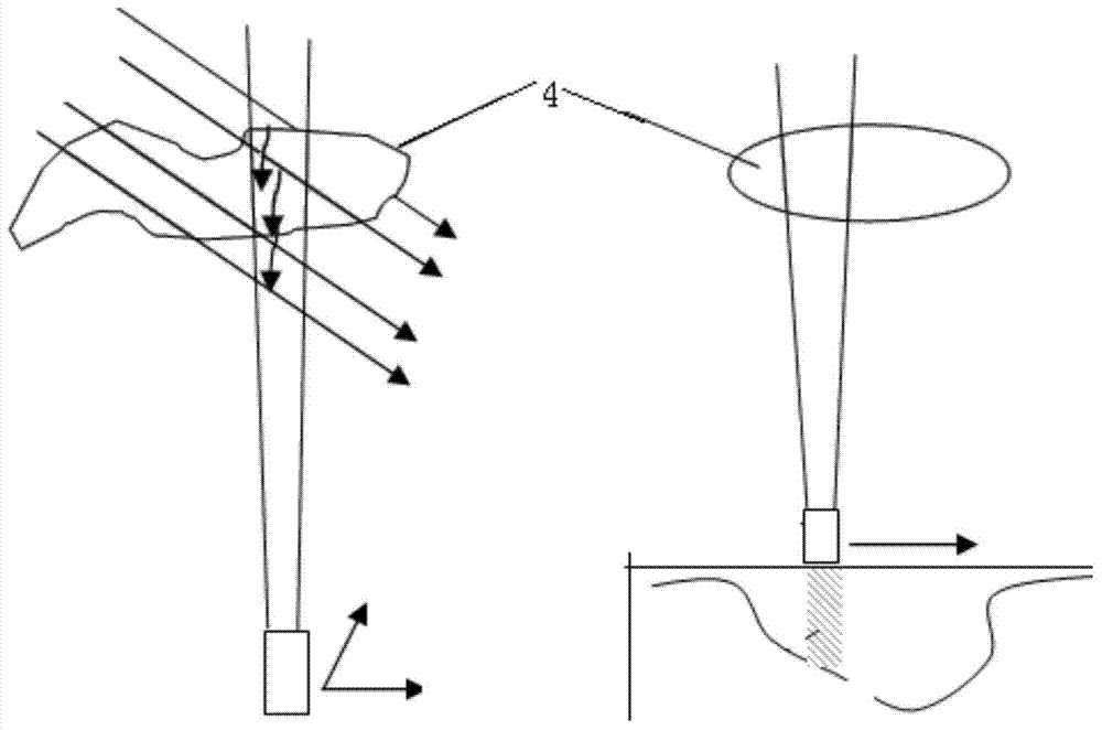
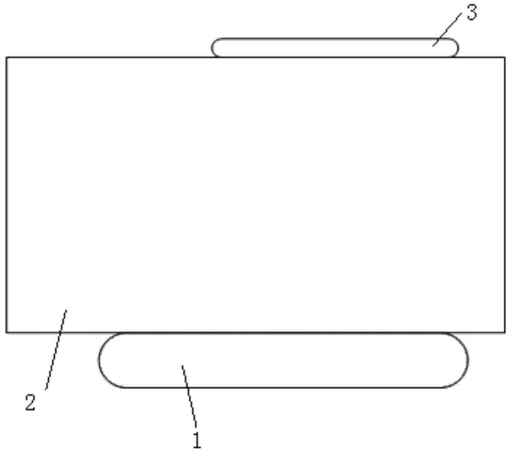
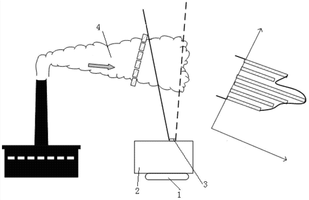
[0020] A method for measuring the emission flux of point pollution sources based on a large-field imaging spectrometer, such as figure 2 As shown, it includes a rotating platform 1, an imaging spectrometer 2 and a reflective large field of view lens 3. The imaging spectrometer 2 is installed on the rotating platform 1, and the reflective large field of view lens 3 is installed on the imaging spectrometer 2, as image 3 As shown, rotate the rotating platform 1 so that the length direction of the slit of the imaging spectrometer 2 is perpendicular to the emission direction of the plume 4, the large field of view of the imaging spectrometer 2 covers the section of the plume 4, and measures the solar scattered light passing through the plume 4 within the angle of view Signal, according to the absorption of polluting gas, use the differential absorption spectrum algorithm to analyze and calculate the concentration of the oblique column of the polluting gas, use the radiation transf...


PUM


Abstract

The invention discloses a point pollution source emission flux measurement method based on a large-visual-field imaging spectrometer. The point pollution source emission flux measurement method comprises the steps of analyzing and calculating the inclined column concentration of a polluted gas by a differential absorption spectroscopy algorithm, converting the inclined column concentration into vertical column density (VCD) through a radiation transfer model, and determining a smoke plume width W(smoke) according to the distribution of distances of the column concentration of the polluted gas, wherein the section concentration V of a smoke plume is equal to VCD*W; measuring the vertical column concentration of the polluted gas at the moment T1, and recording a position S1 of a characteristic value; then, measuring the perpendicular column concentration of the polluted gas at the moment T2, and searching a position S2 of the characteristic value which is recorded at the moment T1; and calculating the discharging speed V(smoke) of the smoke plume according to the records. The point pollution source emission flux measurement method is used for measuring the section concentration of the smoke plume and the discharging speed of the smoke plume, and a point pollution source emission flux can be obtained by multiplying the two measured results. The structure is simple, errors are small, and the measurement precision and the efficiency are high.

Description

technical field [0001] The invention relates to the technical field of environmental monitoring, in particular to a method for measuring emission flux of point pollution sources based on a large-field imaging spectrometer. Background technique [0002] According to the spatial distribution of discharged pollutants, it can be divided into point pollution sources and surface pollution sources. Point pollution sources refer to individual pollution sources that emit pollutants in a small area. The emission flux of pollution sources or the inventory data of pollution sources need to be grasped and updated in a timely manner, so that the environmental protection management department can grasp the real environmental conditions, formulate reasonable and feasible emission reduction plans, and ensure good environmental quality. [0003] At present, there are two conventional methods for point source emission flux. One is to install detection instruments on the chimney to measure the...

Claims


Application Information

Patent Timeline
Patent Type & Authority Applications(China)
IPC IPC(8): G01N21/31
Inventor 司福祺窦科周海金江宇李传新黄书华
Owner ANHUI INST OF OPTICS & FINE MECHANICS - CHINESE ACAD OF SCI
Why Eureka
Try Eureka