Fuel cell

一种燃料电池、电解质膜的技术,应用在燃料电池、燃料电池的零部件、电路等方向,能够解决电解质膜1损害等问题

Active Publication Date: 2014-01-29
HONDA MOTOR CO LTD
View PDF7 Cites 3 Cited by
  • Summary
  • Abstract
  • Description
  • Claims
  • Application Information

AI Technical Summary

Problems solved by technology

Accordingly, the portion of the electrolyte membrane 1 facing the outer peripheral end of the metal separator is easily damaged by the eluted metal ions.

Method used


Image

  • Fuel cell
  • Fuel cell
  • Fuel cell

Examples


Embodiment Construction

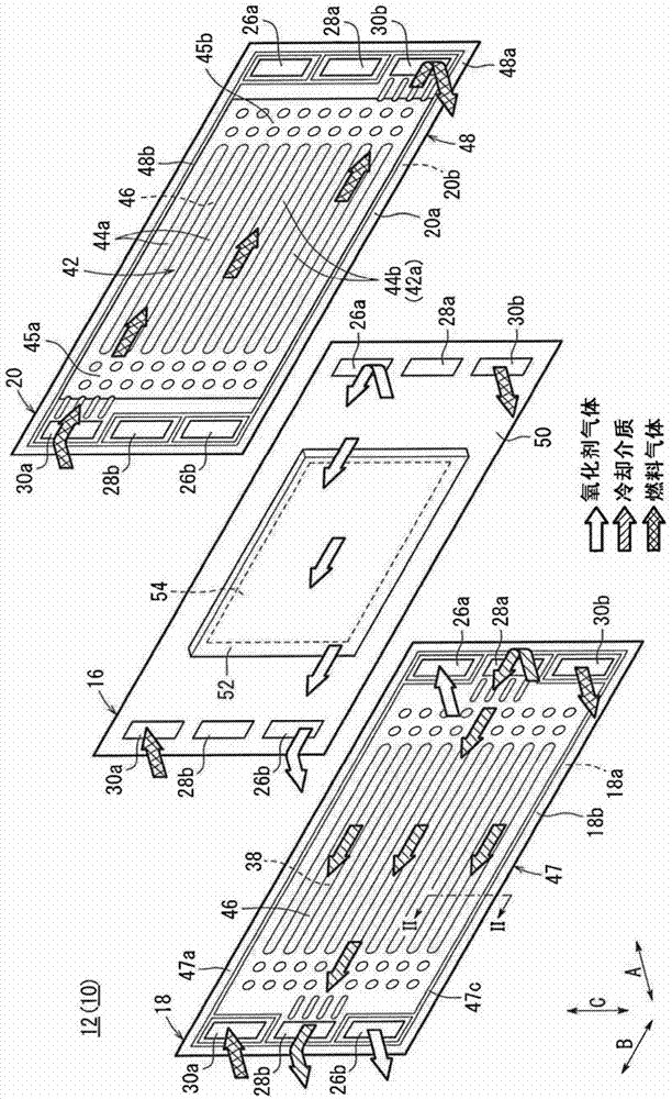
[0043] like figure 1 and figure 2 As shown, in the fuel cell 10 according to the first embodiment of the present invention, a plurality of power generating elements 12 are stacked in the horizontal direction (direction of arrow A), for example, in an upright posture.

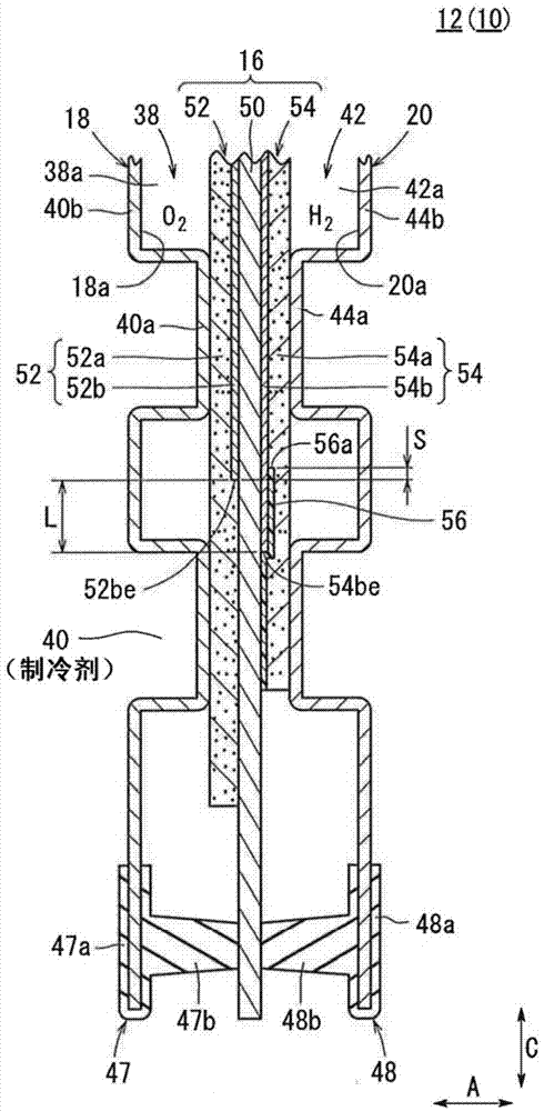
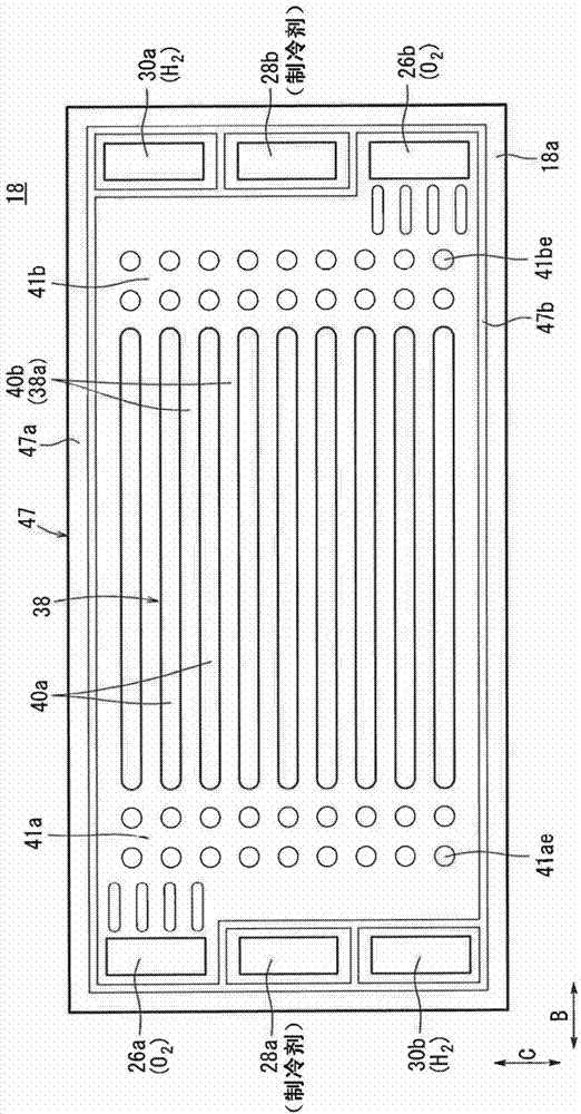
[0044] The power generating element 12 has a horizontally wide shape, and includes an electrolyte membrane electrode assembly (MEA) 16 , and first metal separators 18 and second metal separators 20 sandwiching the electrolyte membrane electrode assembly 16 . The first metal separator 18 and the second metal separator 20 have cross-sectional concave-convex shapes by stamping thin metal plates into corrugated shapes (refer to figure 2 ).

[0045] The first metal separator 18 and the second metal separator 20 are formed of, for example, an aluminum plate, a stainless steel plate, a titanium plate, or a niobium plate.

[0046] In the long side direction of the power generating element 12 ( figure 1 In the arro...


PUM


Abstract

A membrane electrode assembly (16) of a fuel cell (10) includes a solid polymer electrolyte membrane (50), a cathode (52), and an anode (54). The surface size of a cathode side electrode catalyst layer (52b) of the cathode (52) is smaller than the surface size of an anode side electrode catalyst layer (54b) of the anode (54). An inner end (56a) of a gas impermeable film (56) provided around the anode side electrode catalyst layer (54b) and an outer end (52be) of a cathode side electrode catalyst layer (52b) are overlapped with each other on both sides of the solid polymer electrolyte membrane (50).

Description

technical field [0001] The present invention relates to a fuel cell in which a first electrode having a first electrode catalyst layer and a first gas diffusion layer is provided on one side of a solid polymer electrolyte membrane, and on the other side of the solid polymer electrolyte membrane An electrolyte membrane electrode structure in which a second electrode having a second electrode catalyst layer and a second gas diffusion layer is provided on the surface, and the planar size of the first electrode catalyst layer is set to be smaller than that of the second electrode catalyst layer is composed of Clamped by a pair of metal partitions. Background technique [0002] For example, a solid polymer fuel cell is composed of an electrolyte membrane electrode assembly (MEA) in which an anode electrode and a cathode electrode are respectively provided on both sides of a solid polymer electrolyte membrane composed of a polymer ion exchange membrane. The power generation eleme...

Claims


Application Information

Patent Timeline
Patent Type & Authority Applications(China)
IPC IPC(8): H01M8/02
CPCY02E60/521Y02E60/50H01M8/1006H01M8/0273H01M2008/1095H01M8/1007
Inventor 山崎惠子古山雅孝加藤高士神马亮隅英明涩谷将嵩
Owner HONDA MOTOR CO LTD
Why Eureka
Try Eureka