Solder resist composition and printed-circuit board
A technology for printed circuit boards and compositions, applied in the directions of printed circuit, printed circuit, printed circuit manufacturing, etc., can solve the problems of deterioration of white solder mask, reduced reflectivity, deterioration of solder mask, etc., and achieves excellent resolution, improved Acid resistance effect
- Summary
- Abstract
- Description
- Claims
- Application Information
AI Technical Summary
Problems solved by technology
Method used
Image
Examples
Embodiment
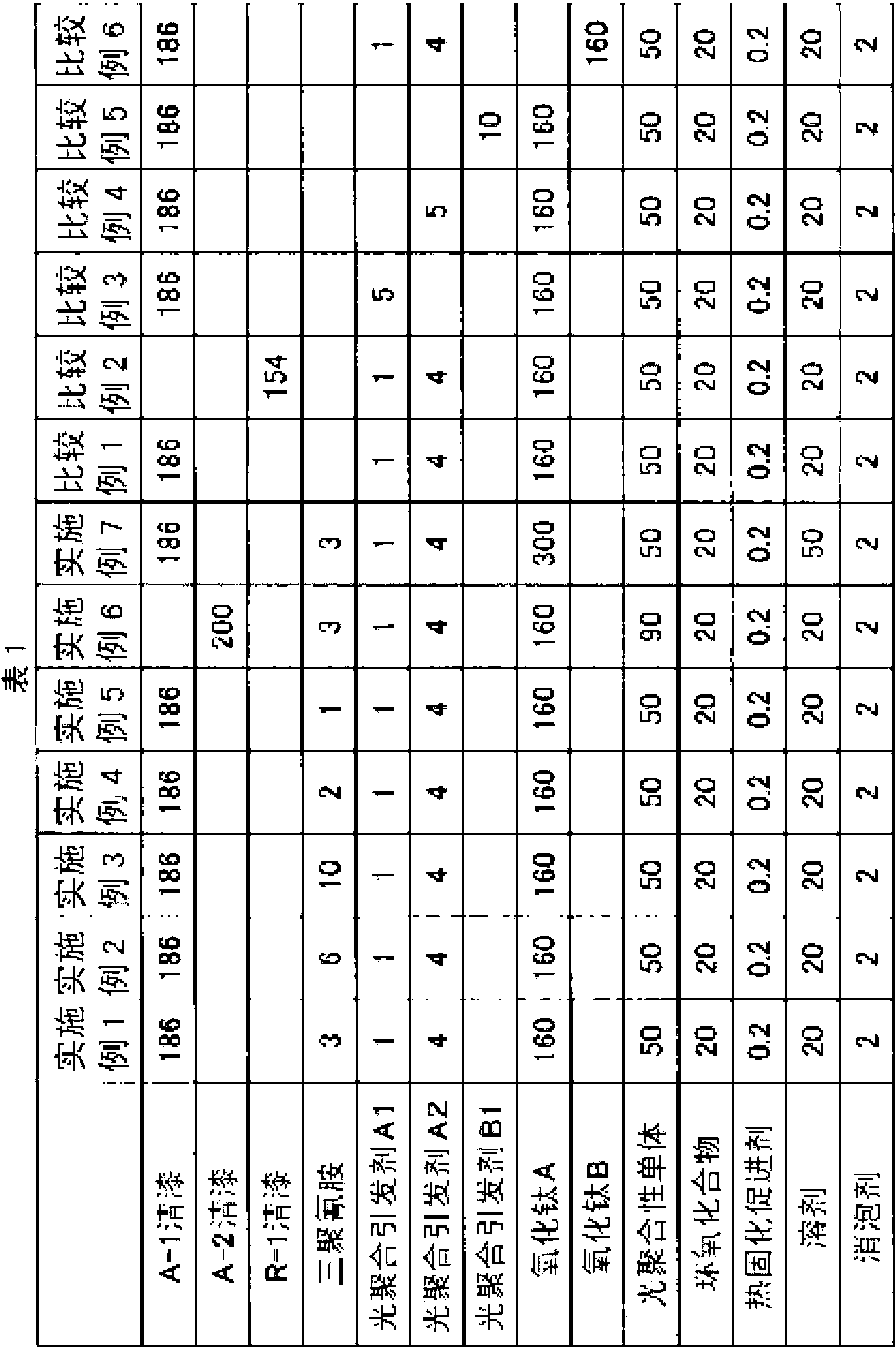
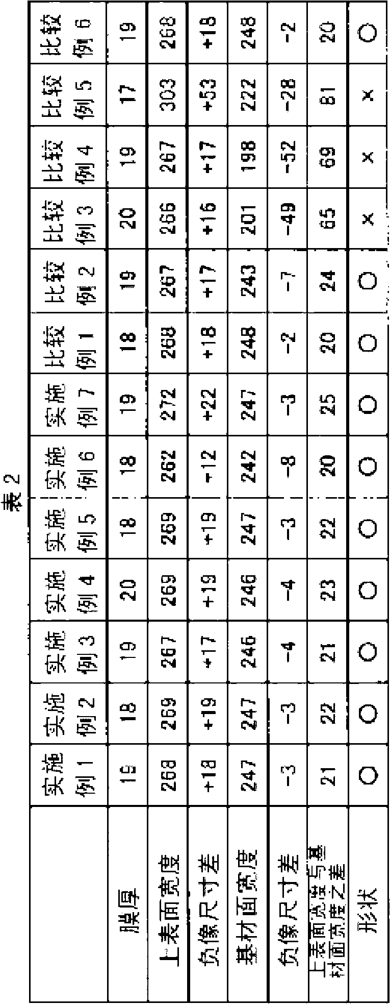
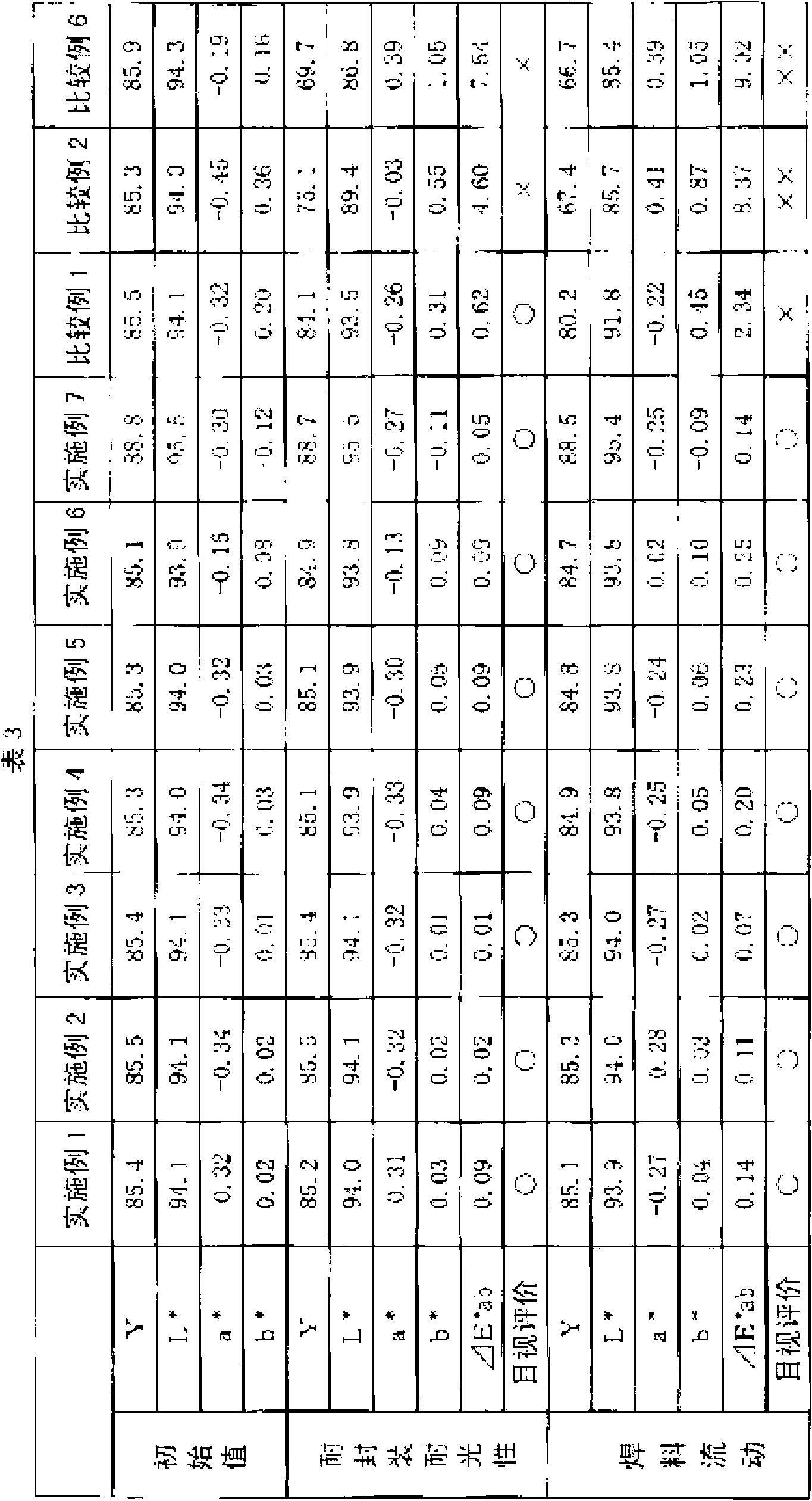
[0082] Hereinafter, although an Example and a comparative example are shown and this invention is demonstrated concretely, this invention is not limited to them at all.
[0083] (A) Synthesis of carboxyl-containing resin
Synthetic example 1
[0085] 900 g of diethylene glycol dimethyl ether as a solvent and 21.4 g of peroxide (2 -Ethylhexanoic acid) tert-butyl (manufactured by NOF Corporation, trade name; PERBUTYL O), heated to 90°C. After heating, 309.9 g of methacrylic acid, 116.4 g of methyl methacrylate, and 109.8 g of lactone-modified 2-hydroxyethyl methacrylate (manufactured by Daicel Corporation., trade name; Placcel FM1) were added dropwise thereto over 3 hours. ) and 21.4 g of bis(4-tert-butylcyclohexyl)peroxydicarbonate (manufactured by NOF Corporation, trade name; PEROYL TCP) as a polymerization initiator. Furthermore, this was aged for 6 hours to obtain a carboxyl group-containing copolymer resin. Here, these reactions were carried out under nitrogen atmosphere.
[0086] Next, 363.9 g of 3,4-epoxycyclohexylmethyl acrylate (manufactured by Daicel Corporation, trade name; Cyclomer-A200), 3.6 g of dimethylbenzyl as a ring-opening catalyst were added to the obtained carboxyl group-containing copolymer res...
Synthetic example 2
[0088] In a flask equipped with a thermometer, a stirrer, a dropping funnel, and a reflux condenser, add diethylene glycol monoethyl ether acetate as a solvent, azobisisobutyronitrile as a catalyst, and heat it to 80 °C under a nitrogen atmosphere. °C, dropwise added monomers in which methacrylic acid and methyl methacrylate were mixed at a molar ratio of 0.40:0.60 over about 2 hours. Furthermore, after stirring this for 1 hour, the temperature was raised to 115 degreeC, it deactivated, and the resin solution was obtained.
[0089] After cooling the resin solution, use tetrabutylammonium bromide as a catalyst, and add butyl glycidyl ether to the carboxyl group of the obtained resin at a molar ratio of 0.40 under the condition of 95~105°C for 30 hours. React and cool.
[0090] Further, tetrahydrophthalic anhydride was added to the OH group of the resin obtained above at a molar ratio of 0.26 at 95 to 105° C. for 8 hours. It was taken out after cooling, and a solution containi...
PUM
| Property | Measurement | Unit |
|---|---|---|
| Acid value | aaaaa | aaaaa |
| Acid value | aaaaa | aaaaa |
Abstract
Description
Claims
Application Information
 - R&D
- Intellectual Property
- Life Sciences
- Materials
- Tech Scout
- Unparalleled Data Quality
- Higher Quality Content
- 60% Fewer Hallucinations
Browse by: Latest US Patents, China's latest patents, Technical Efficacy Thesaurus, Application Domain, Technology Topic, Popular Technical Reports.
© 2025 PatSnap. All rights reserved.Legal|Privacy policy|Modern Slavery Act Transparency Statement|Sitemap|About US| Contact US: help@patsnap.com


