XRAM pulse generation circuit

A technology for generating circuits and pulses, which is applied in the field of XRAM pulse generating circuits, can solve problems such as low output efficiency and small output current of XRAM circuits, and achieve the effects of reducing energy loss, small delay jitter, and strong flow capacity

Inactive Publication Date: 2014-01-29
NORTHWEST INST OF NUCLEAR TECH
View PDF2 Cites 10 Cited by
  • Summary
  • Abstract
  • Description
  • Claims
  • Application Information

AI Technical Summary

Problems solved by technology

[0006] In order to avoid the deficiencies of the prior art, the present invention proposes an XRAM pulse generation circuit. Aiming at the problems of low output current and low output efficiency of the existing XRAM circuit, a new type of XRAM pulse generation circuit is proposed, which improves the flow capacity and improves output efficiency

Method used


Image

  • XRAM pulse generation circuit
  • XRAM pulse generation circuit

Examples


Embodiment Construction

[0018] Now in conjunction with embodiment, accompanying drawing, the present invention will be further described:

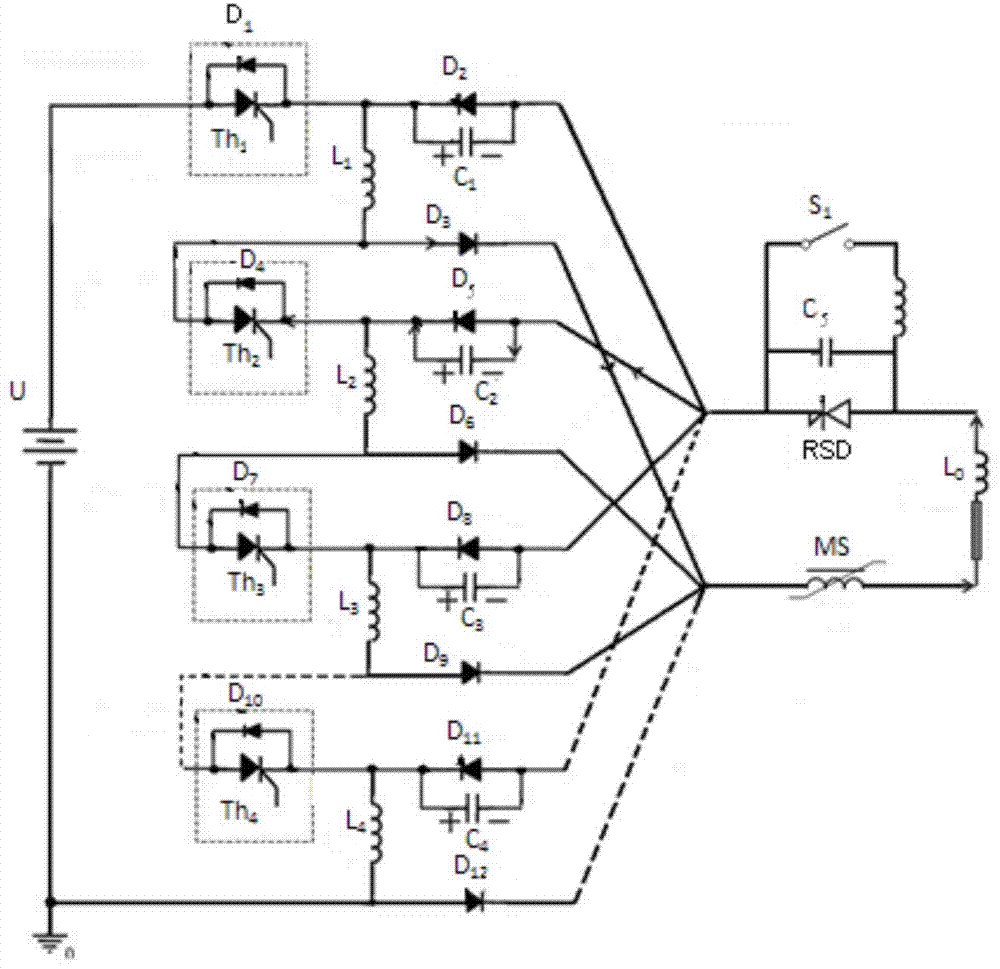
[0019] The circuit diagram of the embodiment of the present invention can be divided into three parts: the primary charging circuit, the commutation circuit and the main discharge circuit. 1 Inductance L 1 , freewheeling diode D 1 antiparallel to Th 1 Both ends, then connect thyristor Th 2 and inductance L 2 , freewheeling diode D 4 antiparallel to Th 2 Both ends, then thyristor Th 3 and inductance L 3 , freewheeling diode D 7 antiparallel to Th 3 Both ends, then connect thyristor Th 4 and inductance L 4 , freewheeling diode D 10 antiparallel to Th 4 Both ends, and then connected to the ground terminal of the power supply. The main discharge circuit consists of RSD switch, load inductance L 0 and magnetic switch MS etc., RSD trigger switch S 1 and capacitance C 5 Connect in parallel to both ends of the RSD switch. The commutation circuit is divi...


PUM


Abstract

The invention relates to an XRAM pulse generation circuit. A reverse switching dynistor (RSD) is selected as a master switch, is a novel high-power semiconductor closing switch and is high in through-current capability and small in current change rate and delay jitter. A fast recovery thyristor is selected as a primary switch to reduce energy loss in the process of current conversion, so that output efficiency is improved. The XRAM pulse generation circuit has the advantages that peak current, current change rate and output efficiency of output pulses can be improved. By current conversion technology, current conversion capability of a unit inductance energy-storage system can reach tens of kA, the unit inductance energy-storage system is matched with a high energy-storage density battery or a small flywheel generator, a lot of inductance energy-storage units are in parallel-connection running, and a high-power pulse power source system with energy storage from hundreds of kJ to several MJ can be realized.

Description

technical field [0001] The invention relates to an XRAM pulse generating circuit, which is mainly used in a pulse power system to generate low-voltage, high-current high-power pulses. Background technique [0002] Pulse power technology compresses energy on a time scale to obtain high power pulses. The traditional Marx circuit uses multiple capacitors to be charged in parallel by a voltage source and discharged in series by closing a switch to realize voltage superposition and power amplification. The XRAM circuit uses multiple inductors to be charged in series by a current source, and is discharged in parallel through a circuit breaker to realize current superposition and power amplification. Compared with the capacitor energy storage method, the energy storage density of the inductor is an order of magnitude higher. In addition, the inductor can generate a large current at a very low voltage, thereby greatly reducing the requirements for the primary power supply. Inducto...

Claims


Application Information

Patent Timeline
Patent Type & Authority Applications(China)
IPC IPC(8): H02M9/02
Inventor 王海洋何小平谢霖燊张国伟陈维青陈志强郭帆贾伟李俊娜汤俊萍孙凤荣
Owner NORTHWEST INST OF NUCLEAR TECH
Why Eureka
Try Eureka