
A grating cooling device for positioning detection of stepping heating furnace

A technology for positioning detection and cooling device, applied in the direction of heat treatment furnace, furnace, furnace type, etc., can solve the problems of combustion fan surge, high cost of compressed air consumption, high cost of spare parts, improve equipment service life, ensure heat treatment performance, Ensure proper positioning

Active Publication Date: 2015-09-02
JIANGSU VALIN XIGANG SPECIAL STEEL
View PDF4 Cites 0 Cited by
  • Summary
  • Abstract
  • Description
  • Claims
  • Application Information

AI Technical Summary

Problems solved by technology

[0008] (4) The area of ​​the grating panel and grating emission source is 50cm each 2 , the outlet area of ​​the purified compressed air cooling pipe is 2cm 2 ;The pipe outlet area is too small, the cooling effect is not good
[0009] 2. Make an impact
[0010] (1) The amount of purified compressed air is large, and the pressure loss of the purified compressed air pipe network is large
[0011] The compressed air consumption of each heating furnace is 1000m 3 / h or more, if only one line and two heating furnaces are used, the pressure of the purified compressed air will be reduced to below 0.35Mpa, while the normal gas source pressure of the furnace is around 0.6Mpa, and the pressure below 0.35Mpa will cause the emergency shutdown of the heating furnace significant impact on production;
[0012] (2) The cooling effect of the grating reflective panel is not good, the grating equipment is easily damaged, and the cost of spare parts is high
[0013] In actual production, it is found that the surface temperature of the grating reflective panel reaches above 200°C. If it is used for a long time at such a high temperature, the panel is very easy to burn out; if the spare parts cannot be replaced in time, the production cannot be normal and automatic, and it is difficult for the operator to control the heating time of the heat treatment furnace. , which makes it difficult to substantially control the heat treatment performance of steel pipes;
[0014] (3) The surrounding noise is extremely loud. When the heat treatment furnace is in normal use, the monitoring sound is above 110 decibels, which seriously affects the working environment of the personnel in the production operation area;
[0015] (4) High cost of compressed air consumption per ton of steel
[0016] After calculation, it is found that the average output of the heat treatment furnace is 25 tons / hour, and the compressed air consumption is 2000m 3 / h, cost per ton of steel: 2000*0.13 / 25=10.4 yuan / ton; annual output of 250,000 tons, cost increase=25*10.4=2.6 million yuan
[0017] There is another problem, the combustion fan will have a surge phenomenon:
[0018] The air generated by the combustion-supporting fan of the walking heating furnace directly enters the air heat exchanger. The pressure of the combustion-supporting air in the walking furnace is above 4.5KPa. When the heat treatment furnace is in the heat preservation state, the air and gas regulating valve switches must be adjusted to reduce the amount of combustion-supporting air to keep warm , but the combustion-supporting fan is designed to supply a large amount of air. When the wind pressure is kept constant, the air volume will decrease, and the wind will accumulate inside the combustion-supporting fan. The combustion-supporting fan will have a surge phenomenon, which will seriously affect the service life of the fan.

Method used


Image

  • A grating cooling device for positioning detection of stepping heating furnace
  • A grating cooling device for positioning detection of stepping heating furnace
  • A grating cooling device for positioning detection of stepping heating furnace

Examples


Embodiment Construction

[0039] The present invention will be further explained below in conjunction with the accompanying drawings and specific embodiments. It should be understood that the following specific embodiments are only used to illustrate the present invention and are not intended to limit the scope of the present invention. It should be noted that the words "front", "rear", "left", "right", "upper" and "lower" used in the following description refer to the directions in the drawings, and the words "inner" and "outer ” refer to directions towards or away from the geometric center of a particular part, respectively.

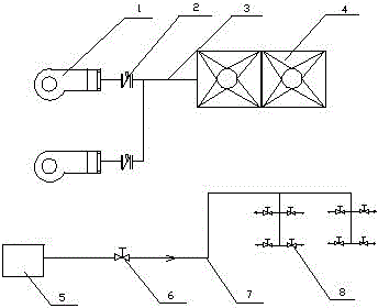
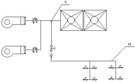
[0040] The present invention is a transformation of the cooling device of the grating detection system of the walking heating furnace. The air supply device of the air compressor and the combustion-supporting fan of the walking heating furnace injecting wind into the air heat exchanger are two sets of irrelevant devices, such as figure 1 As shown, the modified scheme is as foll...


PUM


Abstract

The invention belongs to the field of technical reform of mechanical equipment, and particularly relates to a grating cooling device for positioning and detecting a stepping heating furnace. According to the invention, the ventilating pipe of a combustion fan is provided with a cooling pipeline connected to a grating cooling air source to substitute for a purified compressed air cooling grating detection system; an air curtain is formed on a hot smoke gas outlet by adopting multipoint annular indirect cooling to directly obstruct the overflow of a hot smoke gas inside a furnace cavity, the burning loss on grating and a reflecting plate can be prevented by continuously diluting the hot smoke gas, in such a way, the compressed air is not consumed any longer during improvement, so that the energy resources are saved, and the wind inside the combustion fan of the stepping heating furnace can be shunt; the combustion fan can not generate the phenomenon of surging any longer, so that the service life of the combustion fan is prolonged, and two purposes are achieved at one stroke.

Description

technical field [0001] The invention belongs to the technical transformation of mechanical equipment, and in particular relates to a cooling device for a positioning detection grating of a walking heating furnace. Background technique [0002] The positioning of the stepping furnace steel pipe (steel billet) into the furnace is through grating detection and positioning. The grating light source is irradiated vertically on the reflective panel through the collimating lens, and then received by the photoelectric element. After conversion by the silicon photocell, a sine wave electrical signal can be obtained and provided to The grating signal counting and direction discrimination circuit is used for measuring and counting. [0003] Generally, the grating cooling device for the positioning detection of the walking heating furnace includes a walking heating furnace, a grating, a reflective panel, a roller table and a pipe. The outlet of the flue gas, the grating and the ref...

Claims


Application Information

Patent Timeline
Patent Type & Authority Patents(China)
IPC IPC(8): C21D11/00C21D9/70
Inventor 丁言垒丁晓星
Owner JIANGSU VALIN XIGANG SPECIAL STEEL
Learn More