Refrigeration cycling device

A circulation device and switching device technology, applied in the direction of reversible cycle compressors, refrigerators, refrigeration components, etc., can solve the problems of cost increase, gas refrigerant popularization restrictions, etc., to reduce expansion loss, simple structure, improve heating effect of ability

Inactive Publication Date: 2014-02-05
GUANGDONG MEIZHI COMPRESSOR
5 Cites 70 Cited by

AI-Extracted Technical Summary

Problems solved by technology

In addition, the most popular household air conditioner with a rotary compressor must consider the cost increa...

Method used

[0051] Thus, the first cylinder 10a inhales the low-pressure refrigerant passing through the evaporator, and the second cylinder 10b inhales the gas refrigerant generated in the gas-liquid separator 108. The high-pressure refrigerant discharged from the independent cylinders respectively passes through the first muffler 25a and the second muffler 25b and then flows out from the exhaust pipe 3, thus, the structure is simple, and the refrigeration capacity and efficiency are improved. In addition, power consumption can be reduced by stopping the compre...

Abstract

The invention discloses a refrigeration cycling device comprising a double-cylinder rotary compressor, a liquid accumulator, an indoor heat exchanger, an outdoor heat exchanger, a gas-liquid separator and a medium-pressure gas suction pipe. The double-cylinder rotary compressor comprises a shell provided with an exhaust pipe, a motor and a compression device, the compression device comprises a first cylinder provided with a first compression cavity and a first silencer and a second cylinder provided with a second compression cavity and a second silencer, and the first silencer and the second silencer are communicated with the exhaust pipe; the liquid accumulator is connected to the first compression cavity through a low-pressure gas suction pipe; the gas-liquid separator is connected between the indoor heat exchanger and the outdoor heat exchanger; the medium-pressure gas suction pipe is connected between the second compression cavity and the gas-liquid separator. The refrigeration cycling device is simple in structure, and refrigerating capacity is enhanced and efficiency is improved.

Application Domain

CompressorCompression machines with reversible cycle

Technology Topic

EngineeringCompression device +7

Image

  • Refrigeration cycling device
  • Refrigeration cycling device
  • Refrigeration cycling device

Examples

  • Experimental program(5)

Example Embodiment

[0064] [Example 1]
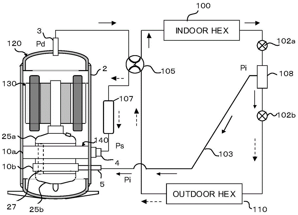
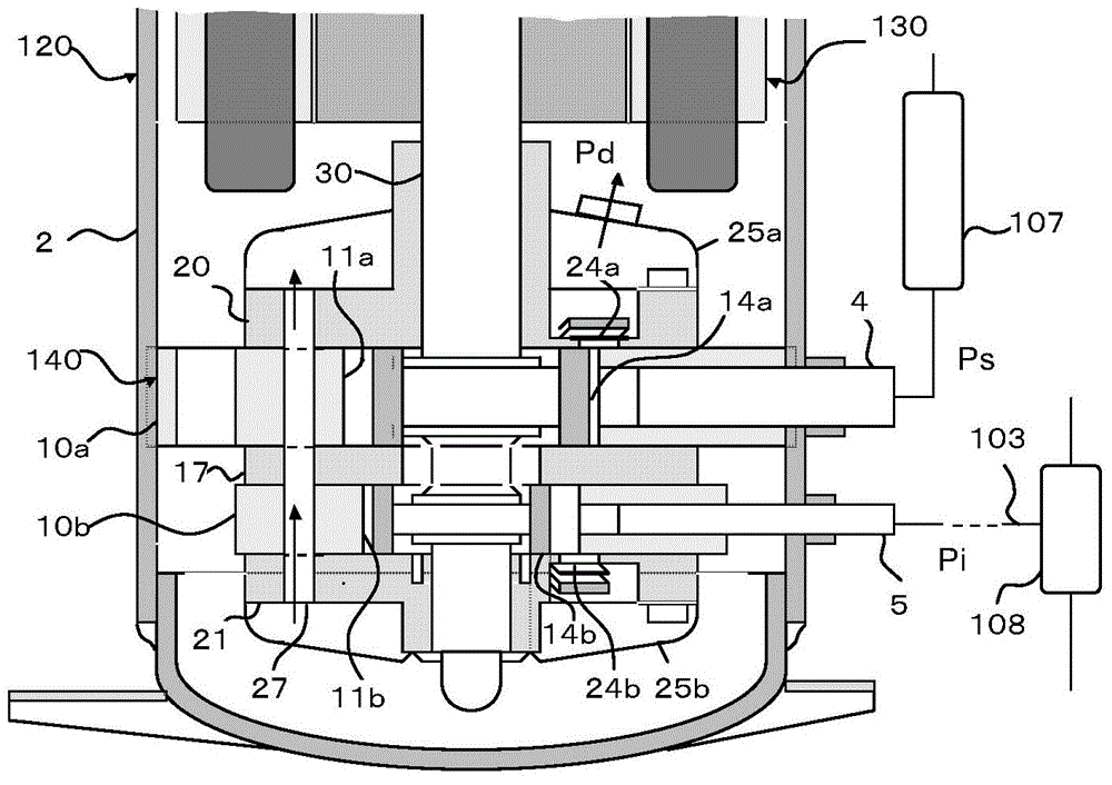
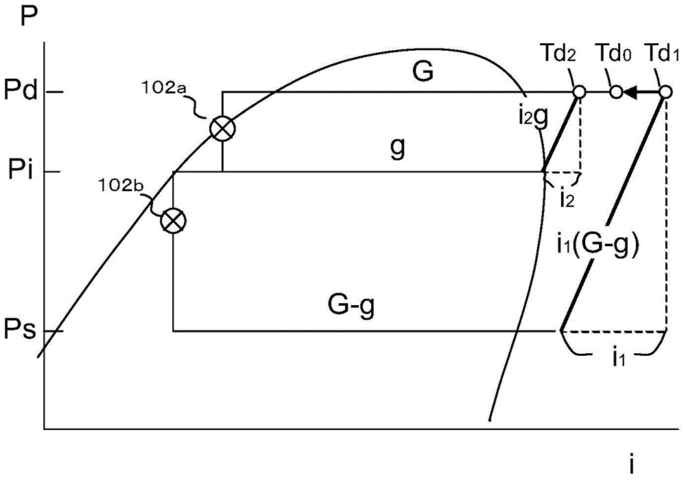
[0065] figure 1 The illustrated two-cylinder rotary compressor 120 is composed of an inverter-type motor unit 130 whose rotation speed can be changed on a sealed casing 2 and a compression element 140 arranged under the motor unit 130. The high-pressure gas refrigerant (pressure Pd) discharged from the exhaust pipe 3 passes through the four-way valve 105 and becomes the condensed refrigerant in the indoor heat exchanger 100. After that, the pressure is reduced by the first expansion valve 102a. The liquid separator 108 is separated into a medium-pressure gas refrigerant (pressure Pi) and a liquid refrigerant. Therefore, the supercooling of the liquid refrigerant increases.
[0066] The liquid refrigerant continues to pass through the second expansion valve 102b to reduce pressure and becomes a low-pressure gas refrigerant (pressure PS) in the outdoor heat exchanger 110. After that, it passes through the four-way valve 105 and the accumulator 107, and is connected to the first cylinder 10a. Flow into the low-pressure suction pipe. In addition, the above two expansion valves are electronic expansion valves that can control the flow of refrigerant. figure 1 The solid line (→) shows the flow direction of the high-pressure refrigerant and the medium-pressure gas refrigerant (Pi), and the dashed line (——> ) Shows the flow direction of low pressure refrigerant (PS).
[0067] Inhaled from the low-pressure suction pipe 4 into the first compression chamber 11a of the first cylinder 10a ( figure 2 (Shown) the compressed high-pressure gas refrigerant is discharged into the first muffler 25a. On the other hand, the gas refrigerant (pressure Pi) separated in the gas-liquid separator 108 passes through the refrigerant delivery pipe 103 and is sucked from the intermediate pressure suction pipe 5 into the second compression chamber 11b of the second cylinder 10b (such as figure 2 Shown). The high-pressure refrigerant compressed in the second compression chamber 11b is discharged into the second muffler 25b. The high-pressure refrigerant of the second muffler 25b passes through the communication hole 27 and merges with the high-pressure refrigerant of the first muffler 25a. Therefore, refrigerants of different temperatures are mixed to become refrigerants of the same temperature.
[0068] Among them, those of ordinary skill in the art should understand that the range of the pressure value Pd of the high pressure gas refrigerant discharged from the two-cylinder rotary compressor, the range of the pressure value Pi of the intermediate pressure gas refrigerant, and the pressure value Ps of the low pressure gas refrigerant range.
[0069] The pressure of the gas refrigerant discharged from the second cylinder 10b is usually the same as the pressure of the gas refrigerant discharged from the first cylinder 10a, and its pressure is the same as the internal pressure of the housing 2 and the high pressure of the exhaust pipe 3 ( Pd) is the same. In addition, the gas refrigerant discharged from the first muffler 25 a is discharged from the exhaust pipe 3 while cooling the motor 130. therefore, figure 1 Shown is a heat pump circulation system with refrigerant circulation. In this case, the feature of Embodiment 1 of the present invention is that the first cylinder 10a and the second cylinder 10b are independent, and although the pressure of the refrigerant sucked in is different from the low-pressure gas (PS) and the intermediate-pressure gas (Pi), each compression chamber The exhaust gas pressure is the same, they merge in the muffler.
[0070] The details of the compression element 140 fixed to the inner diameter of the housing 2 are as follows figure 2 Shown. The compression element 140 is composed of a first cylinder 10a fixed to the inner diameter of the housing 2, a second cylinder 10b fixed by the first cylinder 10a via an intermediate plate 17, and a first compression chamber 11a and a second compression chamber arranged in the center of each cylinder. 11b. The pistons 14a and 14b arranged in them, the sliding plate 12a and the sliding plate 12b that slide reciprocally synchronously with the piston ( Figure 4 Shown), a crankshaft 30 driving its pistons, a main bearing 25 and a secondary bearing 26 that slidably support the crankshaft 30. In addition, the compression angle of the above-mentioned two cylinders is usually at a relative position of 180 degrees.
[0071] The main bearing 25 and the sub-bearing 26 are equipped with exhaust devices with exhaust holes 24a and 24b opened in the first compression chamber 11a and the second compression chamber 11b. It is covered by the first silencer 25a and the second silencer 25b. In addition, refrigerating machine oil (hereinafter referred to simply as oil) for lubricating the compression element 140 is injected into the bottom of the casing 2, which is omitted in the figure.
[0072] The relative displacement ratio of the first compression chamber 11a to the displacement ratio of the second compression chamber 11b can be determined by the ratio of the refrigerant quantity to the injected refrigerant quantity of the circulating refrigeration cycle, the compression ratio Pd/PS and Pd/Pi (absolute Pressure) to set an approximate value. For example, when the motor speed is 60rPS, when Pd=2.54, PS=0.87, Pi=1.50 (MPa.abS), or g/G=0.25, the displacement of the first compression chamber 11a is called Va, due to the compression ratio , The displacement Vb of the second compression chamber 11b is 0.58 times that of the first cylinder 10a, and considering g/G, Vb/Va=0.145. For example, in the case of a domestic air conditioner, when the displacement Va of the first compression chamber 11a is 15cc, when Vb/Va=0.2, the displacement Vb of the second cylinder 10b is 3.0cc. In addition, due to the specifications and design conditions of the air conditioner, Vb/Va varies greatly, and a little margin can be given. The lower limit of the displacement Vb/Va should be 10%, and the upper limit should be 25%.
[0073] As mentioned above, in the design of the small displacement second cylinder 10b, not only the inner diameter of the second compression chamber 11b, but also the height dimension of the second cylinder 10b are also reduced, based on Patent Document 1 (JP 1998-259787, rotary type The publicity technology of sealed compressors and refrigeration cycle devices is wise to omit the sliding vane spring to prevent the decrease of cylinder rigidity and the reduction of sliding area of ​​the sliding vane caused by machining the sliding vane hole. Therefore, the embodiment described later also omits the vane spring of the second cylinder 10b. In addition, if the vane spring is omitted, when the compressor is started, compression starts from the first cylinder 10 with the vane spring, and the second cylinder 10b also starts to compress after a few seconds.
[0074] The function of the second cylinder 10b with a small displacement can be explained as: the refrigerant (Pi) whose pressure is reduced by the first expansion valve 102a is compressed in the second compression chamber 11b and returns to the pressure (Pd) of the housing 2. This design concept is different from the conventional gas refrigerant jet rotary compressor that injects gas refrigerant into the compression chamber or exhaust passage where the pressure changes.
[0075] For example: According to the method disclosed in Patent Document 2 (JP 2000-073974, 2-stage Compressor and Air Conditioning Device) and Patent Document 1, in the first stage compression chamber and the second stage compression chamber that uses 2 cylinders as 2-stage compression A gas refrigerant channel is designed between the compression stages. Its characteristic is to inject a higher pressure gas refrigerant into the refrigerant passing through the intermediate pressure (Pm) of the gas refrigerant passage. Therefore, two refrigerants of different pressures are mixed and flow into the second stage compression chamber. The high-pressure refrigerant compressed again here is discharged into the housing. According to this method, the injection of high-pressure gas refrigerant causes expansion loss. In other words, since the expanded gas energy cannot be recovered, the compression efficiency is reduced. And the structure is more complicated, and piping and a sealed silencer must be added.
[0076] image 3 Shown is the P-h diagram of Example 1. Pd on the vertical axis is the discharge pressure of the first cylinder 10a and the second cylinder 10b, Pi is the injection pressure to the second cylinder 10b, and PS is the suction pressure of the first cylinder 10a. G is the refrigerant flow rate of the indoor heat exchanger 100, and g is the gas refrigerant injection flow rate. Therefore, the refrigerant flow rate of the outdoor heat exchanger 110 is G-g.
[0077] Since the feature of the present invention is that the first cylinder 10a and the second cylinder 10b are independent and compress gases of different pressures, each compression amount (W) can be represented by i1(G-g) and i2(g). Therefore, it can be confirmed again that the second cylinder 10b simply raises the gas refrigerant pressure Pi to the pressure Pd. In addition, even if the pressure Pi fluctuates, the exhaust pressure Pd usually adapts to the case pressure. In addition, if you want to increase or decrease the operating speed (rPS) of the variable speed motor 130, you must increase or decrease the refrigerant flow rate G and heating capacity of the indoor heat exchanger 100 according to its situation. However, due to the first cylinder 10a and the second cylinder 10a The operating speed of the cylinder 10b is generally the same, so the value (ratio) of g/G will not be much different.
[0078] The first embodiment is a reversible refrigeration cycle apparatus equipped with a four-way valve 105, and the four-way valve 105 that switches from the heating mode to the cooling mode may be reversed. At the same time, gas refrigerant injection is performed even in the cooling mode. In addition, Embodiment 1 can be applied to a swing type rotary compressor in which a piston and a sliding vane are integrated.

Example Embodiment

[0079] [Example 2]
[0080] From the viewpoint of the comfort and energy efficiency of air conditioners within one year, there are product plans that do not use gas refrigerant injection in either heating mode or cooling mode, or products that suspend gas refrigerant injection during operation by selecting the mode Planning. In addition, it is necessary to stop the gas refrigerant injection in a state such as late-night operation and dehumidification operation with a small air-conditioning load, or low-load operation after the room temperature has stabilized. As a means to achieve its purpose, the second embodiment is related to the stop or release stop technique of the compression action of the second cylinder 10b with a small displacement.
[0081] First, the design changes of Example 2 compared with Example 1 will be described. Figure 4 Shown is a cross-sectional view of the compression element 140. In the second embodiment, a magnet 16 is provided at the rear end of the second slide groove 17b where the slide 12b is placed. Therefore, the magnetic force of the magnet 16 has the function of holding the stationary slide 12b. So the magnetic force is small. And like Figure 5 As shown, a first two-way valve 106a and a second two-way valve 106b are added. The first two-way valve 106 a is connected to the gas refrigerant delivery pipe 103. The second two-way valve 106b is connected to a high-pressure circuit connecting the exhaust pipe 3 and the four-way valve 105, and a circuit between the first one-way valve 106a and the intermediate pressure suction pipe 5 on the gas refrigerant delivery pipe 103.
[0082] Figure 5 Shown is the heating mode. If the second two-way valve 106b is closed and the first two-way valve 106a is opened at the same time, the gas refrigerant (pressure Pi) of the gas-liquid separator 108 flows into the intermediate pressure suction pipe 5 to form a gas refrigerant injection. The movement of the piston 14b and the sliding plate 12b at this time is as Figure 6a with Figure 6b Shown. But like Figure 7 As shown, if the second two-way valve 106b is opened and the first two-way valve 106a is closed at the same time, at this time, as Figure 8a with Figure 8b As shown, the pressure of the first compression chamber 11b is switched to high pressure (Pd). Since the sliding plate 12b is attracted by the magnet 16 at the top dead center to remain stationary, the piston 14b in the second compression chamber 11b is idling and stops compression . Therefore, the workload of the second cylinder 10b is zero, and the power consumption (W) of the compressor decreases.
[0083] The control of the first two-way valve 106a and the second two-way valve 106b has nothing to do with the switching of the four-way valve 105, and is usually a high-pressure function, so the above principle is also valid in the cooling mode. Therefore, the second embodiment can be controlled by the opening and closing of the first two-way valve 106a and the second two-way valve 106b. Regardless of the operation mode and operating load, the gas refrigerant injection can be stopped and the stop can be cancelled freely, which can be applied to the comfort of air conditioners. And the annual efficiency (APF) is improving.

Example Embodiment

[0084] [Example 3]
[0085] Picture 9 The illustrated embodiment 3 is another application of the embodiment 2, which can be used when the gas refrigerant injection is stopped regardless of the heating mode or the cooling mode state. In the third embodiment, the rotary compressor 120 is used as in the second embodiment. The first two-way valve 106a and the second two-way valve 106b are omitted, and a three-way valve 116 is added.
[0086] Such as Picture 9 As shown, the three-way valve 116 is respectively connected to the intermediate pressure suction pipe 5, the refrigerant delivery pipe 103, and the pipeline between the exhaust pipe 3 and the four-way valve 105, and the intermediate pressure can be selectively sucked through the three-way valve 116 The pipe 5 is in communication with the refrigerant delivery pipe 103. At this time, one end of the pipeline connecting the three-way valve 116 between the exhaust pipe 3 and the four-way valve 105 is closed. Furthermore, the gas refrigerant (pressure Pi) of the gas-liquid separator 108 flows into the intermediate pressure suction pipe 5 to form a gas refrigerant jet. Or, through the three-way valve 116, the pipeline between the medium-pressure suction pipe 5 and the exhaust pipe 3 and the four-way valve 105 can be selectively connected. At this time, the end of the three-way valve 116 connected to the refrigerant delivery pipe 103 is closed. of. Furthermore, the pressure of the first compression chamber 11b is switched to high pressure (Pd), and the piston 14b in the second compression chamber 11b stops idling and compresses according to the same principle as in the second embodiment.

PUM

no PUM

Description & Claims & Application Information

We can also present the details of the Description, Claims and Application information to help users get a comprehensive understanding of the technical details of the patent, such as background art, summary of invention, brief description of drawings, description of embodiments, and other original content. On the other hand, users can also determine the specific scope of protection of the technology through the list of claims; as well as understand the changes in the life cycle of the technology with the presentation of the patent timeline. Login to view more.

Similar technology patents

Photoelectric sensor for position of sun

InactiveCN101650173AEffective tracking range expandedSimple structure
Owner:WUHAN UNIV OF TECH

Magnetic cooling apparatus and control method thereof

ActiveUS20130180263A1simple structure
Owner:SAMSUNG ELECTRONICS CO LTD

Dual-Drivetrain of Power-Assist Vehicle

InactiveUS20100181130A1enhance uphill momentumsimple structure
Owner:CHOU WEN CHENG

Classification and recommendation of technical efficacy words

  • Simple structure
  • Increase heating capacity

Exhaust air heat recovery fresh air unit equipped with moisture absorption heat exchangers

InactiveCN101900384Aincrease evaporating pressureincrease heating capacity
Owner:NANTONG HUAXIN CENT AIR CONDITIONER

Method and device for air conditioner control and air conditioner

ActiveCN113531830Aincrease heating capacityMeet cooling and heating needs
Owner:QINGDAO HAIER AIR CONDITIONER GENERAL CORP LTD +2

Double heat pump and thermoelectric unit coupled heating system and method

PendingCN109579104AIncrease heating capacityincrease flexibility
Owner:XIAN THERMAL POWER RES INST CO LTD
Why Eureka
Try Eureka