A detection method for rotationally symmetric free-form surface lens

A technology of rotational symmetry and curved surface lens, which is applied in the direction of testing optical properties, can solve the problems of free-form surface detection, and achieve the effect of reducing material cost, short processing cycle and high detection accuracy

Inactive Publication Date: 2015-11-18
SUZHOU UNIV
View PDF3 Cites 1 Cited by
  • Summary
  • Abstract
  • Description
  • Claims
  • Application Information

AI Technical Summary

Problems solved by technology

At present, in addition to the contact measurement method using three coordinates as a tool, the traditional interference detection method is almost powerless for the detection of free-form surfaces.

Method used


Image

  • A detection method for rotationally symmetric free-form surface lens
  • A detection method for rotationally symmetric free-form surface lens
  • A detection method for rotationally symmetric free-form surface lens

Examples


Embodiment 1

[0023] In this embodiment, a reflector for detection is designed for a plano-convex lens with a diameter of 30 mm and a plano-convex lens with a high-order aspheric surface on one side. The equation of the high-order aspheric surface of the lens to be tested is:

[0024] ;

[0025] in:

[0026] c=1 / R

[0027] R=20.4

[0028] k=-1.035356

[0029] a2=5.685242e-006

[0030] a3=-7.934483e-010

[0031] a4=-3.635248e-012

[0032] a5=5.883743e-016

[0033] The remaining coefficients are 0;

[0034] The refractive index of the material is n=1.788.

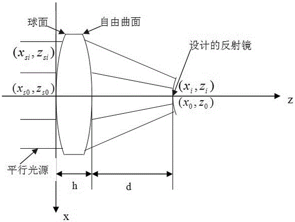
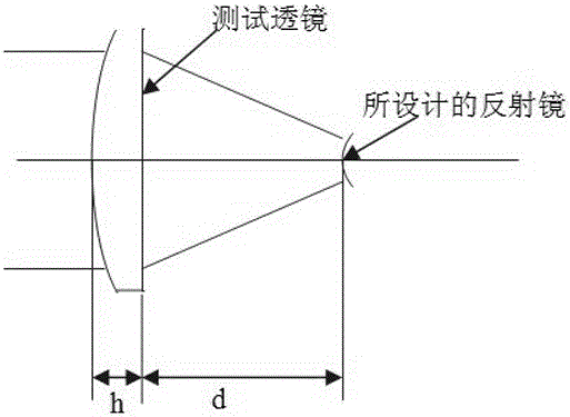
[0035] See attached figure 1 , which is a schematic diagram of the design of the reflector used for the detection of the rotationally symmetric free-form surface lens provided in this embodiment; the specific implementation steps involved in the reflector are as follows:

[0036] 1. Use parallel light as the light source. The incident direction of the parallel light source is parallel to the Z-axis, and the incident direction...


PUM


Abstract

The invention relates to a method for detecting a rotational-symmetry free-form surface lens. A reflector is arranged on a detected optical path, and light which passes through the detected rotational-symmetry free-form surface lens can return along the same way through the reflector, so that interference detection of a rotational-symmetry free-form surface is achieved. The designed reflector is machined through a single-point diamond lathe, so that the final detection accuracy of the reflector is ensured. The method for detecting the rotational-symmetry free-form surface lens is a new method for detecting the rotational-symmetry free-form surface, and compared with a traditional contact-type detection method, the method for detecting the rotational-symmetry free-form surface lens has the advantages of being high in detection speed, efficiency and accuracy; compared with a 3D projection method, higher measurement accuracy can be provided; compared with a CGH detection method, the cost is low, and the work period is short. The method for detecting the rotational-symmetry free-form surface lens is further applicable to detection of any free-form surfaces.

Description

technical field [0001] The invention relates to a detection method for a rotationally symmetrical free-form surface lens, and belongs to the technical field of design, detection and manufacture of optical free-form surfaces. Background technique [0002] Modern optical systems are developing in the direction of small size, light weight, simple structure, and high cost performance. This new feature makes it more and more difficult for traditional optical components to meet the needs of the market. With the continuous development of modern optical design level, the free-form surface optical element can simplify the system structure, reduce the number of lenses, significantly reduce the size of the lens, further improve the imaging quality, and can also obtain excellent characteristics such as special optical performance. , making its application in optical systems more and more important. [0003] Free-form optical components are increasingly used in optoelectronic products ...

Claims


Application Information

Patent Timeline
Patent Type & Authority Patents(China)
IPC IPC(8): G01M11/02
Inventor 仇谷烽崔旭东
Owner SUZHOU UNIV
Why Eureka
Try Eureka