A microgrid converter hardware-in-the-loop system test platform
A loop system and test platform technology, applied in the direction of measuring electrical variables, instruments, measuring electricity, etc., can solve the problems of unsuitable converter research and testing, no converter development, test platform, etc., to achieve good circuit performance and heat dissipation. effect, improve test efficiency and save cost
- Summary
- Abstract
- Description
- Claims
- Application Information
AI Technical Summary
Problems solved by technology
Method used
Image
Examples
specific Embodiment approach
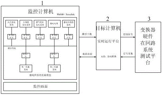
[0040] As described in the accompanying drawings of the description, a microgrid converter hardware-in-the-loop system test platform provided by the present invention is implemented. The test platform is based on the Matlab / Simulink environment to build a microgrid system simulation model and build a converter master at the same time. The circuit and the control circuit realize the communication between the target computer 2 and the converter through the controller interface module 25, and constitute a complete microgrid converter hardware in-loop closed-loop real-time simulation and rapid development system with actual voltage and current feedback. Its specific implementation is as follows:
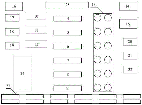
[0041] A microgrid converter hardware-in-the-loop system testing platform, including a monitoring computer 1, a target computer 2, and a converter hardware-in-the-loop system testing platform 3, the monitoring computer 1 is connected to the target computer 2, and the controller interface ...
specific Embodiment 1
[0059] The hardware-in-the-loop system test platform for micro-grid converters provided by the present invention has the advantage of being able to conduct hardware-in-loop simulation tests on developed micro-grid converters to test whether their performance meets requirements. Taking the converter of the battery energy storage device developed by this test platform as an example, further explanation is as follows:
[0060] as attached Figure 9 As shown, after the external battery energy storage device 27 is connected in series with the external inductor 29, it is connected in series with the current acquisition and conditioning module 17 through the interface, and then connected to the input end of the target converter, and the output port of the target converter is connected to the external analog DC bus 28 through the interface connection, while the solar power generation system 30 is connected to the external analog DC bus 28 through the converter; the voltage acquisition...
PUM
 Abstract
Description
Claims
Application Information
 - R&D
- Intellectual Property
- Life Sciences
- Materials
- Tech Scout
- Unparalleled Data Quality
- Higher Quality Content
- 60% Fewer Hallucinations
Browse by: Latest US Patents, China's latest patents, Technical Efficacy Thesaurus, Application Domain, Technology Topic, Popular Technical Reports.
© 2025 PatSnap. All rights reserved.Legal|Privacy policy|Modern Slavery Act Transparency Statement|Sitemap|About US| Contact US: help@patsnap.com


