Power amplifier used for polar coordinate transmitter

A power amplifier and transmitter technology, applied in power amplifiers and other directions, can solve the problems of limited frequency response bandwidth of switching power amplifiers, inability to expand bandwidth, signal distortion, etc., to achieve high power additional efficiency, convenient circuit debugging, and improved waveform effects.

Inactive Publication Date: 2014-02-05
SHANGHAI RADIO EQUIP RES INST
View PDF5 Cites 7 Cited by
  • Summary
  • Abstract
  • Description
  • Claims
  • Application Information

AI Technical Summary

Problems solved by technology

For example, methods such as adding a resonant unit to the output of the class E power amplifier and controlling the drain voltage and current are adopted, but these methods cannot expand the bandwidth of the amplitude modulation, and the amplitude amplification channel with limited bandwidth will cause signal distortion
Due to the high oversampling rate of the pulse modulator, the frequency and bandwidth of the signal entering the power modulator will be very high. Due to the limited frequency response bandwidth of the switching power amplifier, it is very difficult to maintain a high average efficiency in this case

Method used


Image

  • Power amplifier used for polar coordinate transmitter
  • Power amplifier used for polar coordinate transmitter
  • Power amplifier used for polar coordinate transmitter

Examples


Embodiment Construction

[0021] The present invention will be further elaborated below by describing a preferred specific embodiment in detail in conjunction with the accompanying drawings.

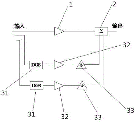
[0022] Such as figure 1 As shown, a power amplifier for a polar coordinate transmitter, the polar coordinate transmitter includes a baseband signal generation module, an amplitude-phase separation module, a modulator, a delay unit, a switching power supply modulator, a phase modulation unit, an amplitude modulation unit and Power amplifier, the output end of the baseband signal generation module is connected to the input end of the amplitude-phase separation module, the two outputs of the amplitude-phase separation module are respectively connected to the input end of the modulator and the input end of the delay unit, and the output end of the modulator is connected to the switching power supply The input end of the modulator, the output end of the switching power supply modulator is connected to the input end of...


PUM


Abstract

The invention discloses a power amplifier used for a polar coordinate transmitter. The power amplifier used for the polar coordinate transmitter comprises a first power amplifier tube, an adder and at least two harmonic injection units; the output end of the first power amplifier tube is connected with the first input end of the adder; each harmonic injection unit comprises defected ground, a power amplifier tube and a moving direction unit which are connected in sequence; the output end of the moving direction unit is connected with the input end of the adder. The defected ground comprises a microstrip line and an incomplete dumbbell structure; the microstrip line is arranged in the middle of the incomplete dumbbell structure. According to the invention, a DGS (defected ground structure) is adopted for injecting harmonic waves for reverse class-F power amplification, the amplitude modulation bandwidth can be increased widely, signal deformation caused by an amplitude-scaling passage can be reduced, and the internal circuit structure can also be simplified and the probability of miniaturization of the polar coordinate transmitter can be achieved.

Description

technical field [0001] The invention relates to a power amplifier of a microwave circuit, in particular to a power amplifier for a polar transmitter. Background technique [0002] The polar transmitter is a high-efficiency transmitter structure and helps to achieve the goal of an all-digital flexible transmitter. The polar coordinate transmitter is different from the rectangular coordinate transmitter. It needs to convert the rectangular coordinate information I / Q into polar coordinate ρ / θ information, amplify them separately, and finally combine them into a rectangular coordinate modulated signal for transmission. The efficiency advantage of polar transmitters is reflected in their ability to use highly efficient power amplifiers. Therefore, it is of great practical significance to study the high-performance and miniaturized polar coordinate transmitter. [0003] In the prior art, the polar coordinate transmitter usually adopts some E-type switching power amplifier struct...

Claims


Application Information

Patent Timeline
Patent Type & Authority Applications(China)
IPC IPC(8): H03F3/20
Inventor 赵世巍汪霆雷蒋开创张翔
Owner SHANGHAI RADIO EQUIP RES INST
Why Eureka
Try Eureka