CMOS compatible silicon differential condenser microphone and method for manufacturing the same

A technology of capacitors and microphones, which is applied in the field of microphones and can solve problems such as inappropriate

Active Publication Date: 2014-02-05
GOERTEK MICROELECTRONICS CO LTD
View PDF2 Cites 48 Cited by
  • Summary
  • Abstract
  • Description
  • Claims
  • Application Information

AI Technical Summary

Problems solved by technology

Also, this structure may not be suitable for integration with other CMOS regulation circuits

Method used


Image

  • CMOS compatible silicon differential condenser microphone and method for manufacturing the same
  • CMOS compatible silicon differential condenser microphone and method for manufacturing the same
  • CMOS compatible silicon differential condenser microphone and method for manufacturing the same

Examples


no. 1 example )

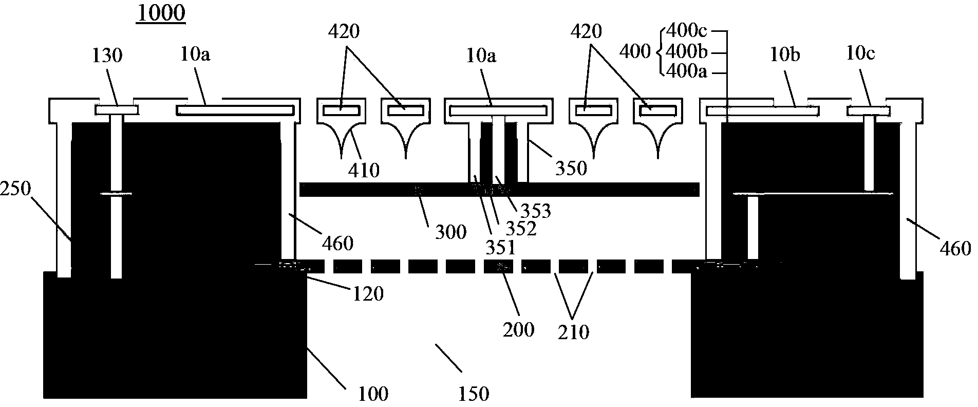
[0023] Below, refer to figure 1 The structure of the CMOS-compatible silicon differential capacitor microphone according to the first embodiment of the present invention will be described.

[0024] figure 1is a cross-sectional view showing the structure of the CMOS-compatible silicon differential capacitor microphone 1000 according to the first embodiment of the present invention. like figure 1 As shown, the CMOS-compatible silicon microphone 1000 according to the first embodiment of the present invention may include a silicon substrate 100 , a lower backplane 200 , an isolator 250 , a compliant diaphragm 300 , interconnection posts 350 and an upper backplane 400 . The diaphragm 300 and the lower back plate 200 form a lower variable capacitor, the diaphragm 300 and the upper back plate 400 form an upper variable capacitor, and the lower variable capacitor and the upper variable capacitor form a differential capacitor.

[0025] like figure 1 As shown, the silicon substrate ...

no. 2 example )

[0061] The following will refer to Figure 4 The structure of the CMOS-compatible silicon differential capacitor microphone 1000' according to the second embodiment of the present invention will be described. Will Figure 4 and figure 1 In contrast, the difference between the second embodiment of the present invention and the first embodiment is that, in the second embodiment, the periphery of the diaphragm 300 is suspended on the upper back plate 400, such as figure 1 In the first embodiment shown, the interconnection post 350 connects the center of the diaphragm 300 to the upper backplane 400 as shown in Figure 4 In the second embodiment shown, the interconnection pillar 350' is located at the periphery of the diaphragm 300, and a via metal 353' is formed in the spacer 250, and the via metal 353' connects the periphery of the conductive diaphragm 300 to the periphery of the diaphragm 300. The lead-out electrodes 10a formed in the upper back plate 400 are used to lead the...


PUM


Abstract

A CMOS compatible silicon differential condenser microphone and a method for manufacturing the same are provided. The microphone(1000) comprises a silicon substrate(100), wherein a CMOS circuitry is accommodated thereon; a first rigid conductive perforated backplate(200) supported on the silicon substrate with an insulating layer(120) inserted therebetween; a second rigid perforated backplate(400) formed above the first backplate, including CMOS passivation layers(400a, 400c) and a metal layer(400b) sandwiched between the CMOS passivation layers as an electrode plate of the second plate, wherein an air gap, with a spacer forming its boundary, is provided between the opposite perforated areas of the first backplate and the second backplate; a compliant diaphragm(300) provided between the first backplate and the second backplate, wherein a back hole(150) is formed to be open in the silicon substrate underneath the first backplate so as to allow sound pass through, and the diaphragm and the first backplate form a first variable condenser, the diaphragm and the second backplate form a second variable condenser, and the first variable condenser and the second variable condenser form differential condensers.

Description

technical field [0001] The invention relates to the technical field of microphones, in particular to a CMOS-compatible silicon differential capacitor microphone and a manufacturing method thereof. Background technique [0002] Silicon-based MEMS microphones widely used in hearing aids, mobile phones, digital cameras and toys are reaching their limits. The need for smaller, cheaper, robust microphones with high sensitivity and low noise levels is endless. Reducing the size of a microphone degrades its performance, such as sensitivity. Today, however, micro-process technology provides very good control over the critical dimensions and characteristics of the microphone, enabling further miniaturization and optimization of the microphone. In addition, more complex MEMS microphone principles (such as a microphone with a differential capacitor and a differential preamplifier) ​​can be applied, so that the performance of the MEMS microphone (such as sensitivity) can be maintained...

Claims


Application Information

Patent Timeline
Patent Type & Authority Applications(China)
IPC IPC(8): H04R19/04H04R19/00
CPCH04R19/00B81B2207/015B81C1/00246H04R19/04B81B3/0078H04R19/005
Inventor 王喆
Owner GOERTEK MICROELECTRONICS CO LTD
Why Eureka
Try Eureka