Cross flow guide type stirring paddle applied to fermentation tank

A cross-flow oriented, impeller technology, used in bioreactor/fermenter combinations, specific-purpose bioreactors/fermenters, mixer accessories, etc., can solve shear damage, microbial growth and normal metabolism. Influence and other problems, to achieve the effect of small shear damage, favorable for gas-liquid two-phase dispersion, and enhanced heat exchange

Active Publication Date: 2014-02-12
JIANGNAN UNIV +1
View PDF6 Cites 9 Cited by
  • Summary
  • Abstract
  • Description
  • Claims
  • Application Information

AI Technical Summary

Problems solved by technology

However, at the end of the impeller, the high shear force generated by high-speed rotation will cause potential damage to microbial cells such as filamentous bacteria, which will adversely affect the growth and normal metabolism of microorganisms

Method used


Image

  • Cross flow guide type stirring paddle applied to fermentation tank
  • Cross flow guide type stirring paddle applied to fermentation tank
  • Cross flow guide type stirring paddle applied to fermentation tank

Examples


Embodiment 1

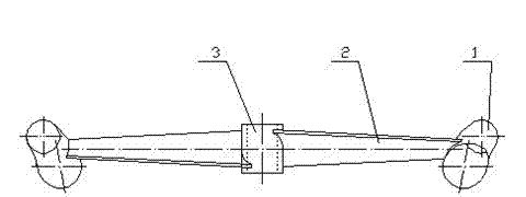
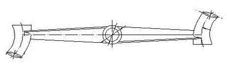
[0022] The cross-flow guiding impeller includes a hub 3, an arc-shaped inclined blade paddle 2 and a cross-flow guiding pipe 1, as shown in the attached Figure 1-2 shown. The hub 3 has a diameter of 35mm and a height of 40mm, and the diameter of the entire stirring paddle is 390mm (from the outer end of the guide tube of one of the two symmetrical blades to the outer end of the guide tube of the other), the arc-shaped inclined blade paddle 2 has a diameter of 330mm (from the inner end of the guide tube of one of the two symmetrical blades to the inner end of the guide tube of the other), the root section size of the arc-shaped inclined blade paddle is (radius R50mm, arc 45o), and the end section size For (radius R50mm, arc 23o). The inlet of the cross-flow guide pipe 1 faces downward and the outlet faces upward, the installation surface of the cross-flow guide pipe and the rotation plane of the stirring paddle form an included angle of 25°, the inlet plane of the cross-flow ...

Embodiment 2

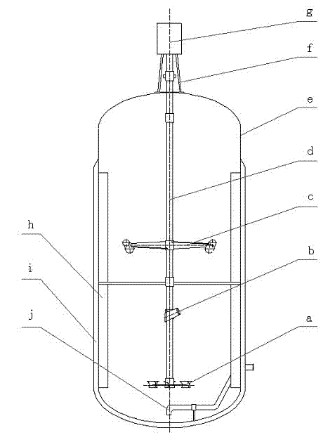
[0024] The cross-flow guiding stirring paddle can be applied in the ventilation fermenter, as attached image 3 shown. The fermenter system mainly includes: a, Chemineer BT-6 stirring paddle; b, cross-flow-guided stirring paddle; c, cross-flow-guided stirring paddle; d, shaft; e, fermentation tank container; f, frame; g, Motor; h, baffle; i, jacket; j, intake pipe. The upper two impellers are cross-flow oriented impellers, and the bottom impellers are Chemineer BT-6 or zigzag symmetrical oblique blade impellers (Chinese patent 200820237972.2). The combined agitation system can be applied to high-viscosity ventilation fermentation process. The bottom paddle diameter (d1) is 1 / 3 of the diameter D of the fermenter, and the distance from the bottom paddle to the bottom of the fermenter is 1.0 d1; the upper two-layer paddle adopts the cross-flow guiding paddle described in the present invention, and the diameter (d2) of the paddle is 2 / 3 of the diameter of the fermentation tank D...


PUM

PropertyMeasurementUnit
diameteraaaaaaaaaa
heightaaaaaaaaaa
diameteraaaaaaaaaa

Abstract

A cross flow guide type stirring paddle applied to a fermentation tank belongs to the technical field of chemical machinery. The stirring paddle comprises a hub 3, a cambered surface inclined-blade paddle 2 and a cross flow guide pipe 1, wherein the hub 3 is a hollow cylinder, the cross section of the cambered surface inclined-blade paddle 2 is an arc bulged upwards, two to four blades of the cambered surface inclined-blade paddle are symmetrically distributed on the hub, and the cross flow guide pipe 1 is arranged at the tail end of the cambered surface inclined-blade paddle. The stirring paddle is mounted on a stirring shaft in the tank, is an axial flow stirring paddle and is applicable to the occasions like liquid-liquid blending, gas-liquid dispersion and forced heat transfer. The fluid in the fermentation tank moves axially under the action of the cambered surface inclined-blade paddle, meanwhile, part of the flow is guided to the rear upper part of the outer side of the blade, shocks on the wall of the tank and forms cross flow with the downward axial flow formed by the cambered surface inclined-blade paddle under the action of the cross flow guide pipe at the tail end of the stirring paddle, so that the fluid blending, gas-liquid dispersion and heat transfer are facilitated. The stirring paddle is relatively simple in blade structure, different specifications and sizes can be made according to the requirements, and the manufacturing cost is low.

Description

technical field [0001] The invention relates to a cross-flow guiding stirring paddle applied to a fermenter, which can be applied to the fields of chemical industry, food, fermentation, papermaking, textile and the like, and belongs to the technical field of chemical machinery. Background technique [0002] The mixing process is one of the most common key unit operations in chemical, biological, pharmaceutical, food, environmental protection and other industries. After nearly a century of experimental research and theoretical exploration, today's fluid mixing technology has entered a period of rapid development, developed a variety of mixing systems with different applications and unique properties, and accumulated a large number of designs that can be used to analyze and predict mixing systems experience and relevance. However, due to the diversity of the fluid mixing system and the complexity of the rheological properties of the material, it is difficult to adopt a unifor...

Claims


Application Information

Patent Timeline
Patent Type & Authority Applications(China)
IPC IPC(8): B01F7/18B01F15/00C12M1/02
Inventor 詹晓北郑志永高敏杰丁春华
Owner JIANGNAN UNIV
Why Eureka
Try Eureka