Wharve of spun yarn spindle

A spindle disk and spindle technology, applied in the direction of textiles and papermaking, etc., can solve the problems of increasing spindle belt tension, reducing yarn quality, and increasing energy consumption of spinning frame, so as to increase friction coefficient, improve yarn quality, and improve transmission efficiency Effect

Inactive Publication Date: 2014-02-12
TONGXIN TEXTILE MACHINERY WUHU
View PDF9 Cites 1 Cited by
  • Summary
  • Abstract
  • Description
  • Claims
  • Application Information

AI Technical Summary

Problems solved by technology

[0004] Due to the smooth surface of the spindle disk used as the spindle pulley for the existing spindle, and the surface of the spindle pulley will become smoother with the passage of time, the friction coefficient between the spindle pulley and the spindle belt will be very low , resulting in severe mutual slippage and reduced transmission efficiency; and the slip coefficient of each spindle of the whole spinning machine is not consistent, and the speed of each spindle varies greatly
A large difference in spindle speed will cause uneven yarn twist and reduce yarn quality
In order to avoid this situation, the usual method is to increase the tension of the spindle belt, which will cause a sharp increase in the energy consumption of the spinning machine

Method used


Image

  • Wharve of spun yarn spindle
  • Wharve of spun yarn spindle
  • Wharve of spun yarn spindle

Examples


Embodiment Construction

[0025] The specific implementation manner of the present invention will be described in further detail below by describing the best embodiment with reference to the accompanying drawings.

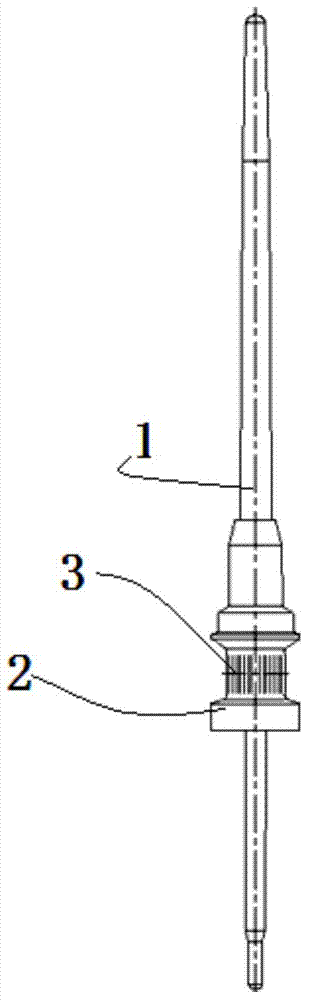
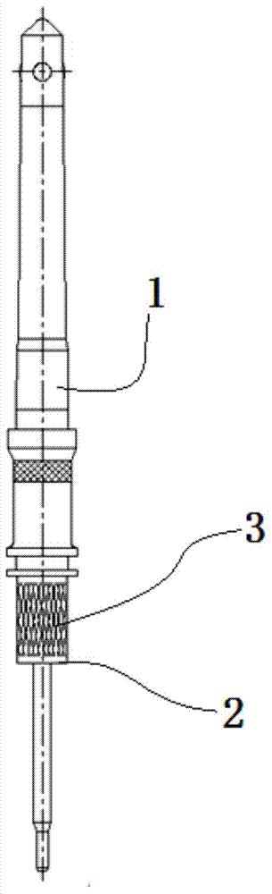
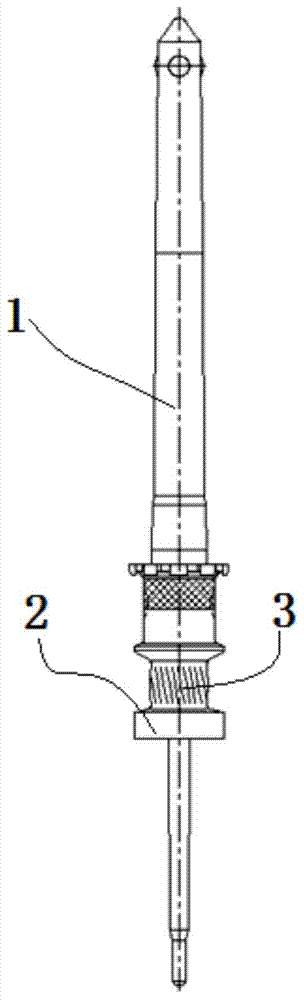
[0026] Such as figure 1 , figure 2 and image 3 As shown, the spinning spindle includes a spindle rod 1, and the spindle disk 2 is arranged on the spindle rod 1. The spindle disk 2 is connected with the spindle belt that drives the spinning spindle to rotate, and the contact surface between the spindle disk 2 and the spindle belt Anti-slip structure 3 is provided on it.

[0027] Preferably, the anti-slip structure 3 is a corrugated structure provided on the surface of the spindle disc 2 .

[0028] Such as figure 1 As shown, as the first preferred solution, the flute structure is a straight line flute uniformly distributed on the surface of the spindle disc 2 along the axial direction of the spindle rod 1 .

[0029] Such as figure 2 As shown, as the second preferred solution, the f...


PUM

PropertyMeasurementUnit
Widthaaaaaaaaaa

Abstract

The invention discloses a wharve of a spun yarn spindle. The spun yarn spindle comprises a spindle blade, wherein the wharve is arranged on the spindle blade; the wharve is connected with a spindle tape driving the spun yarn spindle to rotate; and an anti-slip structure is arranged on the surface where the wharve and the spindle tape are contacted. According to the wharve of the spun yarn spindle, the anti-slip structure can effectively increase the surface friction coefficient of a spindle tape wheel, the skid phenomenon of the spindle tape wheel and the spindle tape is prevented, and the transmission efficiency is improved; and at the same time, the difference of rotating speeds of all spindles of a whole spinning frame can be balanced, and the yarn quality is improved further.

Description

technical field [0001] The invention relates to a textile machinery part, in particular to a spun spindle spindle disc. Background technique [0002] The spinning process is the last process of yarn forming in the ring spinning process. It completes the drafting, twisting and winding of the yarn, and the spinning spindle is a key component of a high-speed spinning frame used in the spinning process. Each The spinning frame is equipped with several hundred to more than one thousand sets to complete the tasks of twisting and winding forming of the yarn count. [0003] The spindle is a high-speed rotating part, and the spindle needs to be driven by power. At present, the driving methods of the spinning spindle mainly include: 1. A group of four spindles is driven by the roller through the spindle belt; 2. The whole spinning frame is driven by a motor through a dragon belt; 3. The electric spindle driven by a single motor. Due to the reasons of manufacturing technology and pro...

Claims


Application Information

Patent Timeline
IPC IPC(8): D01H7/04
Inventor 方保信刘滔吕跃勇
Owner TONGXIN TEXTILE MACHINERY WUHU
Why Eureka
Try Eureka