Multi-level back-grasp-type hollow anchor rod and construction method thereof

A construction method and bolt technology, which are applied in the installation of bolts, earthwork drilling, infrastructure engineering, etc., can solve the problems of difficult installation of bolts, difficulty in forming holes, and waste of materials, so as to achieve good anchoring effects and increase anchorage Force, increase the effect of the contact area

Inactive Publication Date: 2014-02-12
SHANDONG JIAOTONG UNIV
View PDF8 Cites 24 Cited by
  • Summary
  • Abstract
  • Description
  • Claims
  • Application Information

AI Technical Summary

Problems solved by technology

[0002] A large number of anchors are used in tunnel construction, slope protection and foundation pit protection. The anchoring force per unit length of the anchor is often related to the contact area between the anchor and the rock mass. For common anchors, the radial range of anchoring is affected by the diameter of the anchor. However, increasing the diameter of the bolt too much will cause waste of material
And when supporting the top of the tunnel, if the anchor rod is installed in the upward direction, there will be accidents where the anchor rod falls out and hurts people.
Drilling holes in sandy soil and water often has the problem that it is not easy to form holes and the anchor rods are not easy to install.

Method used


Image

  • Multi-level back-grasp-type hollow anchor rod and construction method thereof
  • Multi-level back-grasp-type hollow anchor rod and construction method thereof
  • Multi-level back-grasp-type hollow anchor rod and construction method thereof

Examples


Embodiment Construction

[0019] The present invention will be further described below in conjunction with the accompanying drawings and embodiments.

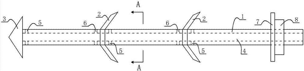
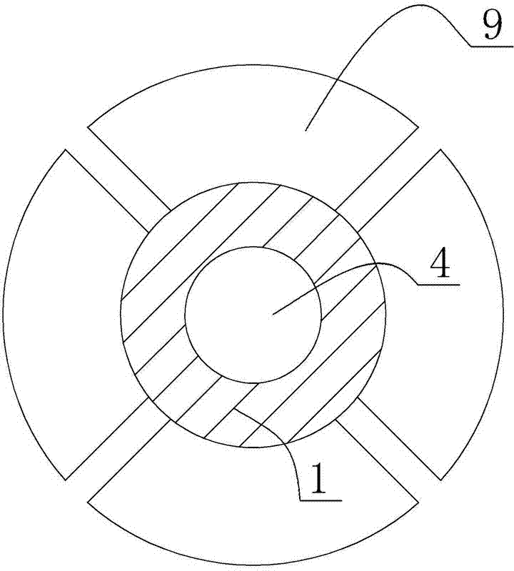
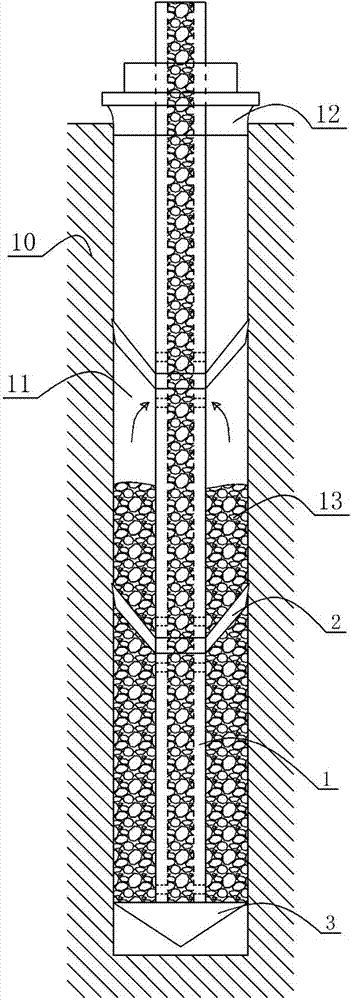
[0020] Such as figure 1 As shown, the structural diagram of the invented inverted hollow anchor is given, which includes an anchor rod 1, an inverted buckle 2, an anchor head 3, a grouting channel 4, a grouting hole 5, a return hole 6, and a backing plate 7 and a nut 8; the anchor rod 1 shown is rod-shaped, and the center of the anchor rod 1 is provided with a grouting channel 4 for injecting cement mortar 13 . The left end of the anchor rod 1 is fixed with an anchor head 3, so that the whole anchor rod is driven into the drilled anchor rod fixing hole 11, or the anchor rod is directly driven into soft soil, sandy soil and water. The anchor rod 1 is evenly fixed with a plurality of upside-down buckles 2, which are bowl-shaped towards the right; It can shrink in the forward direction; when the fastening force is applied through the nut 8, the buckle 2 ...


PUM


Abstract

The invention discloses a multi-level back-grasp-type hollow anchor rod. The multi-level back-grasp-type hollow anchor rod comprises an anchoring rod with a grouting passage inside, an anchor head is fixed at the lower end of the anchoring rod, a plurality of back-grasp buckles are fixed on the anchoring rod, a grout outlet is formed in the anchor head, and the parts, at the upper side of the back-grasp buckles, of the anchoring rod and the parts, at the lower side of the back-grasp buckles, of the anchoring rod are provided with grout outlets and air return holes respectively, and the grout outlets and the air return holes are communicated with the grouting passage. Compared with the construction method of a hard rock body and a soil body, the construction method of the multi-level back-grasp-type hollow anchor rod comprises the steps of (a) preparation of equipment, (b) measurement and distribution of holes, (c) drilling, (d) hole cleaning and detection, (e) inserting of the anchor rod, (f) installation of a grout stop plug, (g) screwing of nuts and (h) grouting, and the anchor rod is directly inserted through the anchor head according to the construction method of a soft soil body, sand and water. The multi-level back-grasp-type hollow anchor rod and the construction method of the multi-level back-grasp-type hollow anchor rod increase the contact area and anchoring force between the anchor rod and the hole wall and prevent the anchor rod from falling out and injuring people. A uniform cement mortar layer can be formed around the anchor rod through the grout outlets and the air return holes, the damage of corrosion is avoided, and the purpose of long-time supporting is achieved.

Description

technical field [0001] The invention belongs to the technical field of rock-soil stability support for tunnel engineering, slope engineering, and deep foundation pit engineering, and more specifically relates to a multi-stage pouring system that can effectively increase the anchoring force and form a uniform thickness of cement mortar. Grab-type hollow anchor rod and its construction method. Background technique [0002] A large number of anchors are used in tunnel construction, slope protection and foundation pit protection. The anchoring force per unit length of the anchor is often related to the contact area between the anchor and the rock mass. For common anchors, the radial range of anchoring is affected by the diameter of the anchor. However, increasing the diameter of the bolt too much will cause waste of material. And when supporting at the top of the tunnel, if the anchor rod is installed in the upward direction, there will be an accident in which the anchor rod f...

Claims


Application Information

Patent Timeline
Patent Type & Authority Applications(China)
IPC IPC(8): E02D5/74E21D21/00E21D20/02
Inventor 李晋郭德栋张起赵之仲
Owner SHANDONG JIAOTONG UNIV
Why Eureka
Try Eureka