Method for controlling common rail pressure limiting valve

A control method and pressure limiting valve technology, applied in electrical control, engine control, fuel injection control, etc., can solve problems such as energy loss, unstable speed, poor quality of fuel injection atomization, etc., and achieve enhanced safety and reliability , avoid insufficient power, fast and reliable closing effect

Active Publication Date: 2014-02-12
CHINA FAW LIMITED WUXI FUEL INJECTIONEQUIP RES INST +1
View PDF8 Cites 16 Cited by
  • Summary
  • Abstract
  • Description
  • Claims
  • Application Information

AI Technical Summary

Problems solved by technology

If the rail pressure is always higher than the closing pressure of the pressure limiting valve, the pressure limiting valve will always be kept open, so that the vehicle is always in a lame driving state, and because the high-pressure fuel is released from the pressure limiting valve, resulting in energy loss, the vehicle Poor power and economy
[0006] 2) If the closing pressure of the pressure limiting valve is relatively low (such as 200bar), once the pressure limiting valve is opened, when the rail pressure drops to a very low level (such as 205bar) due to changes in working conditions, the pressure limiting valve will still not work. If you continue to allow fuel injection at this time, the atomization quality of the fuel injection will inevitably be poor, which will lead to deterioration of combustion and emissions, unstable speed or vibration, lack of power, and in serious cases, the engine will even stall. If fuel injection is disabled, the engine will shut down

Method used


Image

  • Method for controlling common rail pressure limiting valve
  • Method for controlling common rail pressure limiting valve
  • Method for controlling common rail pressure limiting valve

Examples


Embodiment Construction

[0042] The present invention will be further described below in conjunction with specific drawings and embodiments.

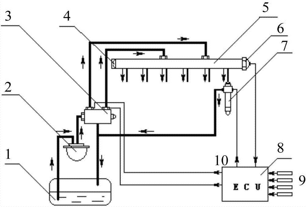
[0043] figure 1 It is a schematic diagram of the high pressure common rail fuel system structure. In the figure, the fuel is sucked from the fuel tank 1 with the primary filter to the fine fuel filter 2, and part of the fuel is pressurized in the plunger chamber of the high-pressure fuel pump 3 to form high-pressure fuel, which flows from the outlet valve port of the fuel pump through the high-pressure fuel pipe and collects into the common rail. The pipe 5 provides a stable and continuous high-pressure fuel source for the high-pressure injection of the fuel injector 7, and the excess part flows back to the fuel tank 1 from the overflow valve on the fuel pump together with the oil returned from the fuel injector 7; the high-pressure fuel flows from the common rail pipe 5 through The high-pressure oil pipe flows to the fuel injector 7 of each cylinder; the fuel...


PUM


Abstract

The invention provides a method for controlling a common rail pressure limiting valve. The method includes the steps of calculating a rail pressure decrease rate, judging whether the limiting valve is opened or not according to the rail pressure decrease rate and a preset opening threshold value, stopping oil supplying and spraying after the pressure limiting valve is opened and when the closing condition of the limiting valve is satisfied, judging whether the pressure limiting valve is closed or not by comparing the rail pressure decrease rate and a closing threshold value, restarting oil supplying and spraying after the pressure limiting valve is judged to be closed, enabling the rail pressure to undergo stable transition to reach a preset rail pressure value, judging whether the fault that the pressure limiting valve can not be closed occurs or not, restarting oil supplying and spraying as well when the pressure limiting valve can not be closed, achieving stable transition of rail pressure, and enabling vehicles to run in a cyllopodia mode. According to the method, the opening state and the closing state of the pressure limiting valve can be rapidly and accurately judged, when an engine is under a frequent zero oil mass state, the pressure limiting valve can be rapidly and reliably closed, an common rail fuel system can restart normal running, and the phenomenon that the pressure limiting valve can not be closed after being open for a long time is avoided.

Description

technical field [0001] The invention relates to a control strategy and method for an electronically controlled high-pressure common rail diesel engine, in particular to a control method for a pressure limiting valve in a common rail fuel injection system. Background technique [0002] Most of the existing patents on the common rail pressure limiting valve are aimed at the structure and fault diagnosis of the pressure limiting valve. For example: Patent No. CN201443451U "Common Rail Pressure Limiting Valve for Engine Common Rail Fuel Injection System" proposes a common rail pressure limiting valve with a new structure, but does not involve the method of judging the opening and closing state of the pressure limiting valve And the control method after the pressure limiting valve is opened. Another example: the patent "control method for an overpressure valve in a common rail fuel supply system" with publication number CN101349230A describes a method for fault diagnosis of a co...

Claims


Application Information

Patent Timeline
Patent Type & Authority Applications(China)
IPC IPC(8): F02D41/22
CPCY02T10/40
Inventor 施华传苏宏亮冯源顾欣李晔费栋梁
Owner CHINA FAW LIMITED WUXI FUEL INJECTIONEQUIP RES INST
Why Eureka
Try Eureka