A non-destructive floor material compression test method and its device

A test device, non-destructive technology, applied in the direction of applying stable tension/pressure to test the strength of materials, and using electrical devices to test fluid tightness, etc., can solve problems such as laborious, frequent repairs, laborious and time-consuming sample preparation, etc. Achieve the effect of improving efficiency and accuracy, saving integration time, and improving production defects

Active Publication Date: 2015-08-19
HONGSEN ELECTRONICS SHANGHAI
View PDF4 Cites 0 Cited by
  • Summary
  • Abstract
  • Description
  • Claims
  • Application Information

AI Technical Summary

Problems solved by technology

These two test methods have problems and shortcomings: 1. The standard raw material has a large area and cannot be tested on the existing universal testing machine, and the raw material needs to be cut into samples
2. The preparation of samples is time-consuming and costly, and the samples cannot be reused regardless of the results
3. Sampling is local and scattered data, which cannot reflect the strength of the overall plate, and it is difficult to organize and analyze data
4. The operation of the test trolley is time-consuming, laborious, and consumes a lot of energy. The cost of testing is high, and the test position is likely to be unable to spread to the entire plate due to the limitation of finished product assembly.
5. Defective products need to be used to know the overall quality, and frequent repairs
6. After the test, the sample is damaged and cannot be used, and the finished products to be used are all parts that have not been tested
In addition, existing detection methods are prone to errors or disputes and cognitive gaps due to inaccurate human operations

Method used


Image

  • A non-destructive floor material compression test method and its device
  • A non-destructive floor material compression test method and its device
  • A non-destructive floor material compression test method and its device

Examples


Embodiment Construction

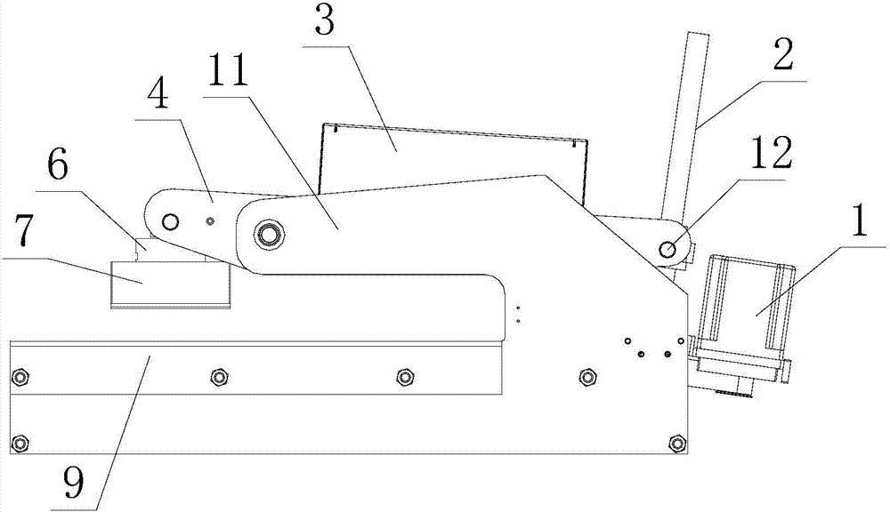
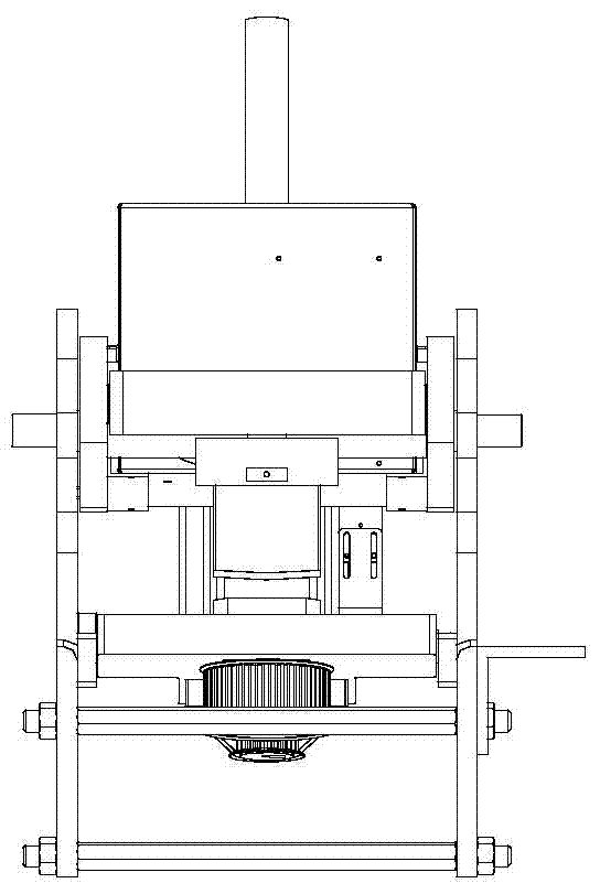
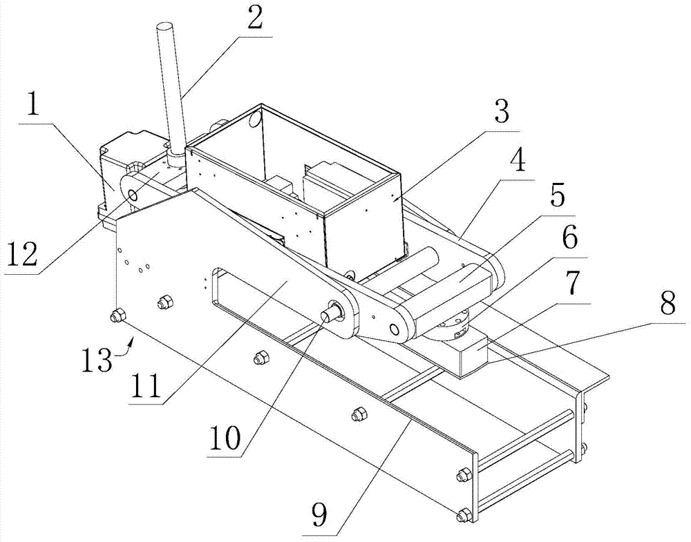
[0032] Below in conjunction with accompanying drawing, the present invention will be further described as follows:

[0033] as attached Figure 1-3 As shown, the present invention comprises: servo motor 1, screw mandrel 2, frame 13 and control part, and described frame 13 is made up of test bench 9 and swing arm 11, and servo motor 1 is housed at the rear end of described test bench 9, The servo motor 1 is equipped with a reducer, the output shaft of the reducer is connected to the screw rod 2, and the screw rod 2 is connected to the lifting seat 12, and the two ends of the lifting seat 12 are connected to the lever bracket through the rotating pin 4, the lever bracket 4 is installed on the front end of the swing arm 11 through the fulcrum shaft 10, the front end of the lever bracket 4 is provided with a rotating support 5, and the bottom of the rotating support 5 is provided with a load cell 6 And the test pressure head 7, the pressure measurement surface of the test pressur...


PUM


Abstract

The invention relates to the technical field of a floor material compression test, and specifically relates to a nondestructive floor material compression test method as well as a device of the nondestructive floor material compression test method. The device comprises a servo motor, a lead screw, a rack and a control part, wherein the rack is composed of a test table and a rotary arm; the servo motor is arranged at the rear end of the test table; the output shaft of the servo motor is connected with the lead screw in a matched manner; the lead screw is connected with a lifting base in the matched manner; the two ends of the lifting base are connected with the rear end of a lever bracket by a rotary pin roll; the lever bracket is arranged at the front end of the rotary arm by a pivot rotary shaft; a rotary supporting piece is arranged at the front end of the lever bracket; a weighing sensor and a test pressure head are arranged on the bottom of the rotary supporting piece. According to the invention, a tested material or sample is not wasted, a great number of sampling expenses of labor are saved, test data teaming time is saved, efficiency and precision are improved, loss increase caused by reworking or scraping as defective products are mixed in subsequent flow is avoided, full-inspection operation can be achieved by expansion, and production quality is stable.

Description

[technical field] [0001] The invention relates to the technical field of floor material compression testing, in particular to a non-destructive floor material compression testing method and a device thereof. [Background technique] [0002] At present, there are two existing test methods for plate strength: Method 1. Use a universal testing machine with a test head to conduct a bending destructive test. During the test, take a sample of 50cm×50cm for destructive testing, and obtain relevant load and deformation data. . Method 2: After the actual assembly, use the test trolley to carry out repeated rolling tests with counterweights. These two test methods have problems and shortcomings: 1. The standard raw material has a large area and cannot be tested on the existing universal testing machine, and the raw material needs to be cut into samples. 2. The preparation of samples is time-consuming and costly, and the samples cannot be reused regardless of the results. 3. Sampling...

Claims


Application Information

Patent Timeline
Patent Type & Authority Patents(China)
IPC IPC(8): G01N3/08G01M3/40
Inventor 陈嘉树
Owner HONGSEN ELECTRONICS SHANGHAI
Why Eureka
Try Eureka