
cs-rz to nrz code conversion fiber grating design method and device

A CS-RZ, fiber grating technology, applied in the field of optical network communication, can solve problems such as poor filtering effect, high cost, and no provision, and achieves suppression of code pattern effect and ripple pulsation, easy to use and operate, and good filtering effect. Effect

Inactive Publication Date: 2016-04-06
FOSHAN UNIVERSITY +1
View PDF5 Cites 0 Cited by
  • Summary
  • Abstract
  • Description
  • Claims
  • Application Information

AI Technical Summary

Problems solved by technology

Its disadvantages are: 1. Due to the use of DI and other interferometer structures, the adjustment operation is more difficult and the cost is relatively high; 2. The scheme of cascaded filters using interferometers actually uses two filters to double the frequency spectrum. It does not provide the technology of cutting and forming directly with only one filter, which leads to the relative complexity of the existing technology and the relatively high cost, which is not conducive to batch use in commercial systems; 3. The filtering effect is insufficient Good, the pattern effect is obvious

Method used


Image

  • cs-rz to nrz code conversion fiber grating design method and device
  • cs-rz to nrz code conversion fiber grating design method and device
  • cs-rz to nrz code conversion fiber grating design method and device

Examples


Embodiment 1

[0053] The following takes a single-channel 20Gbit / s all-optical CS-RZ to NRZ code conversion design method as an example.

[0054] Step 1: Given a set of streams with a length of 2 n -1 pseudo-random code, according to the public method, the discretized digital description of CS-RZ code and NRZ code when the duty cycle is 67% and the signal rate is 20Gbit / s, that is, the discretized numerical sequence S CS-RZ (t) and S NRZ (t).

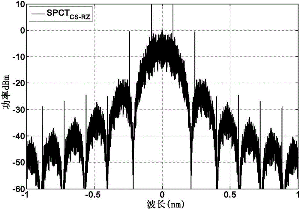
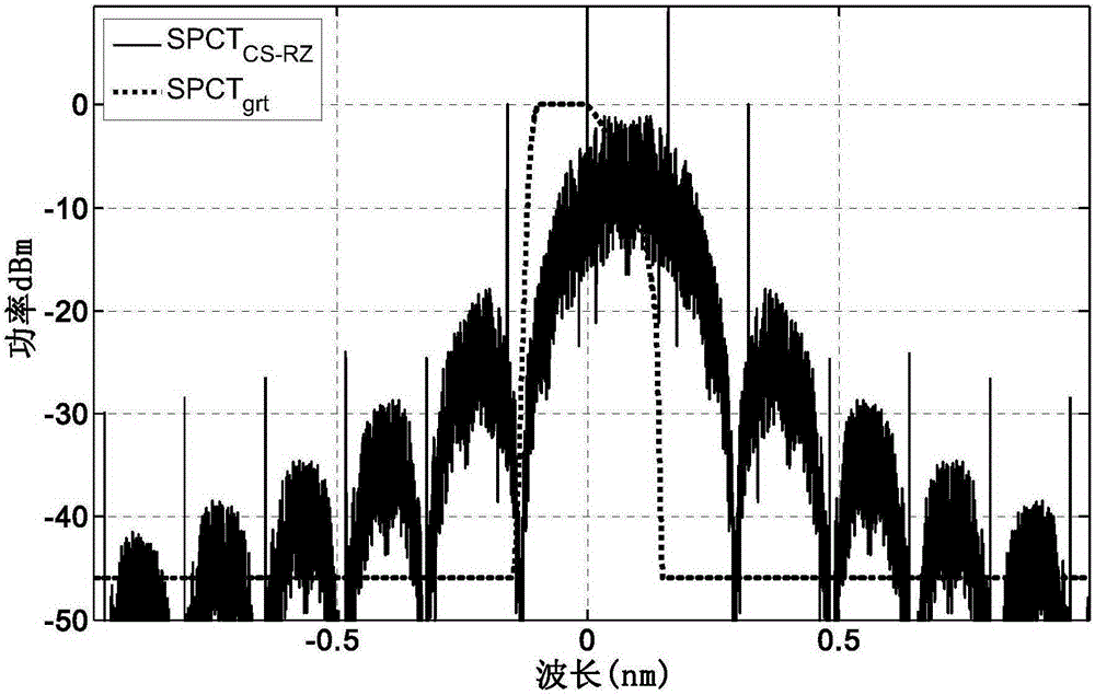
[0055] The second step: to S CS-RZ (t) and S NRZ (t) Perform fast Fourier transform on these two sets of discretized numerical sequences, in decibels, to obtain the discretized numerical sequence SPCT of the power spectrum of the two org_CS-RZ (Δλ) and SPCT NRZ (Δλ). Such as Figure 5 As shown, the solid line represents the SPCT NRZ (Δλ), the dotted line indicates SPCT org_CS-RZ (Δλ)), that is:

[0056] S_FFT CS-RZ =FFT(S CS-RZ (t))

[0057] S_FFT NRZ =FFT(S NRZ (t))

[0058] SPCT org_CS-RZ (Δλ)=10*log(S_FFT CS-RZ ×S_FFT CS-RZ * / ...

Embodiment 2

[0078] The following takes a multi-channel 40Gbit / s all-optical CS-RZ to NRZ code conversion design method as an example. Its device such as Figure 15 As shown, the circulator 4 includes three ports A, B, and C, and the fiber grating includes two ports, the first port 1 of the grating and the second port 2 of the grating. The WDM CS-RZ signal to be converted is input from the A port of the circulator 4, output from the C port of the circulator, enters the first port 1 of the grating, is reflected by the main body of the fiber grating, and is output from the first port 1 of the grating, and enters from the C port of the circulator Circulator, and output from the B port of the circulator to get 40Gbit / sWDMNRZ signal. Figure 16 is the eye diagram of the converted NRZ pattern signal, Figure 17 is the reflection spectrum of a 4-channel fiber grating. Because the code-converted signal is output from the first port 1 of the grating, the characteristic spectrum here is the refle...


PUM


Abstract

The invention discloses a CS-RZ to RZ code type conversion fiber bragg grating designing method and a device thereof. The method comprises the steps of giving a group of pseudo-random codes, acquiring a discretization number value sequence of CS-RZ codes and a discretization number sequence of NRZ codes according to the given duty ratio and the signal rate, carrying out fast fourier transform on the two discretization number value sequences to obtain discretization number value sequences to two power spectrums, blue shifting or red shifting the central wavelength of a discretization number value sequence of a power spectrum of a CS-RZ signal at the wavelength width corresponding to the bit rate of a half CS-RZ signal to obtain a CS-RZ signal spectrum, using a discretization number value sequence of an NRZ power spectrum to subtract the CS-RZ signal spectrum to obtain a new discretization number value sequence, choosing a cutting window with the cutting width corresponding to the wavelength widths of the bit rates of two CS-RZ signals to cut the new discretization number value sequence to obtain a complete characteristic spectrum of a fiber bragg grating and utilizing a reversed layer peeling method to obtain a grating structure. The device is good in filtering effect, can effectively restrain code pattern effect and ripple wave pulsation and can acquire higher Q values.

Description

technical field [0001] The invention relates to the technical field of optical network communication, in particular to an all-optical code conversion device from carrier suppression return-to-zero code (CS-RZ) to non-return-to-zero code (NRZ). Background technique [0002] On the one hand, future high-speed and large-capacity optical communication systems will integrate Dense Wavelength Division Multiplexing (DWDM) and Optical Time Division Multiplexing (OTDM) technologies to increase transmission capacity and speed. On the other hand, in order to further increase the transmission capacity of the optical communication system and increase the spectral efficiency (SE for short), many new modulation formats with high spectral efficiency and unique transmission characteristics will be adopted. New modulation technology has become one of the key technologies in high-speed systems. With the deepening of people's research on modulation technology, in addition to the traditional mo...

Claims


Application Information

Patent Timeline
Patent Type & Authority Patents(China)
IPC IPC(8): G02B5/18G02F1/365
Inventor 左军余宇杨怡曼曹辉梁佩莹
Owner FOSHAN UNIVERSITY
Learn More