
Pinhole photographic lens with micro-lens array

A technology of microlens array and photographic lens, which is applied in TV, color TV, camera, etc., to achieve the effects of environmental protection, low cost and improved imaging quality

Inactive Publication Date: 2014-02-12
张培洲
View PDF0 Cites 0 Cited by
  • Summary
  • Abstract
  • Description
  • Claims
  • Application Information

AI Technical Summary

Problems solved by technology

[0005] In order to solve the shortcomings of existing pinhole cameras and take digital pinhole photos at a lower cost, the present invention provides a new type of pinhole photography lens, which can be used with existing digital cameras and can also shoot pinholes using large-format films camera effect

Method used


Image

  • Pinhole photographic lens with micro-lens array
  • Pinhole photographic lens with micro-lens array
  • Pinhole photographic lens with micro-lens array

Examples


Embodiment Construction

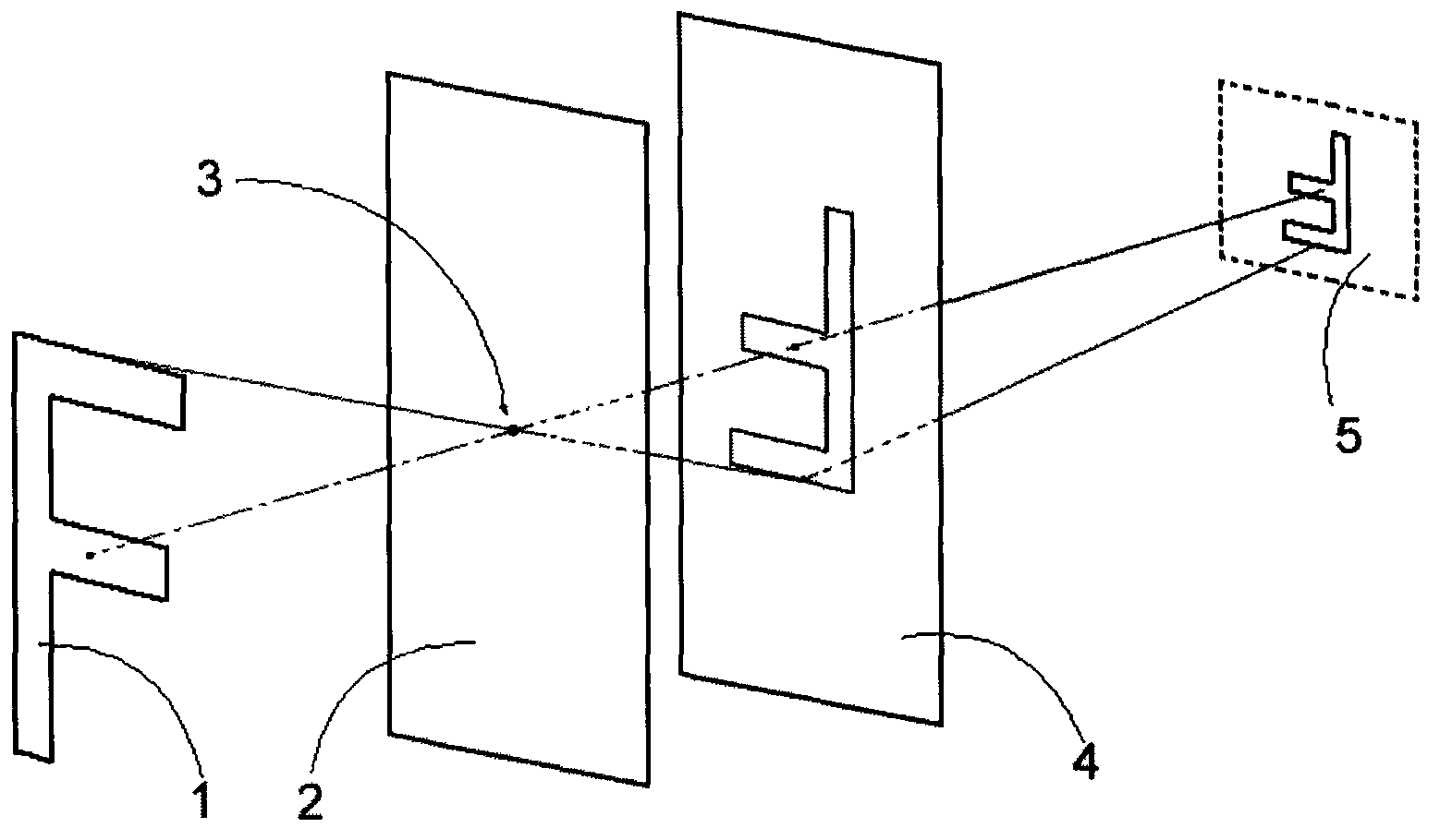
[0022] exist figure 1 Among them, the light from the subject 1 passes through the pinhole 3 and is transmitted to the microlens array 4. The microlens array redirects the light in a regular manner and projects it onto the image sensor 5 of the camera at a small incident angle, and records it as a photo. .

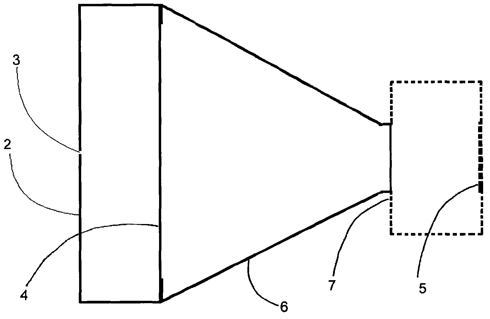
[0023] exist figure 2 In the example shown, the front baffle 2 and the lens barrel 6 form a light-proof cassette, the pinhole is located in the center of the front baffle, the microlens array is placed inside the cassette, parallel to the front baffle, and the end of the lens barrel is installed on the interchangeable lens The camera body, the light from the pinhole is directly projected onto the image sensor of the camera after being converged by the microlens array.

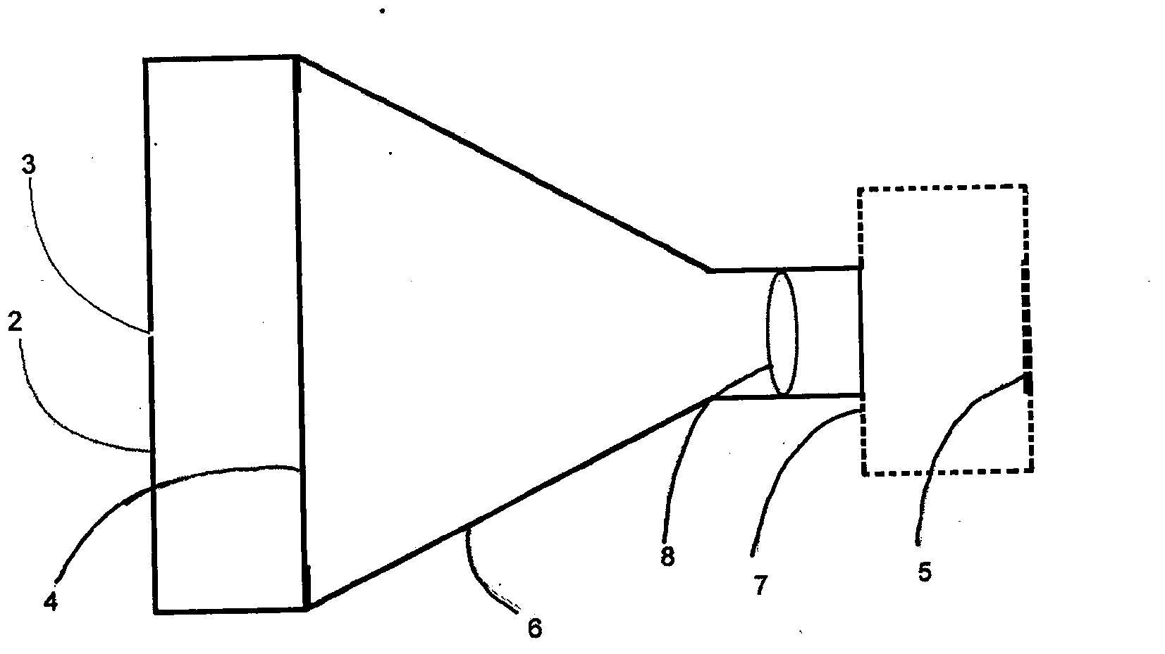
[0024] exist image 3 In the example shown, the front baffle 2 and the lens barrel 6 form a light-proof cassette, the pinhole is located in the center of the front baffle, the microlens array is placed i...


PUM


Abstract

The invention discloses a pinhole photographic lens with a micro-lens array. The micro-lens array replaces a photographic film of a traditional pinhole camera. The pinhole photographic lens with the micro-lens array is installed on a camera body of a digital camera with an interchangeable lens or is connected to the front portion of a lens of a small digital camera in a sleeved mode, imaging is achieved directly through an image sensor of the digital camera, and exposure is controlled through a shutter of the camera.

Description

Technical field: [0001] The invention relates to a novel pinhole photographic lens, which is used in conjunction with a digital camera and can directly take digital pinhole photos with a large viewing angle. Background technique: [0002] Pinhole imaging is an ancient imaging technique. The pinhole camera has unique characteristics such as large depth of field, large viewing angle, hazy imaging, strong perspective without distortion, and natural vignetting. It is popular among professional photographers who pursue unique imaging effects and artistic atmosphere. Favored by teachers and photographers. [0003] At present, the pinhole photography creation mainly uses film to directly expose the pinhole image, which has disadvantages such as difficulty in framing, long processing cycle, difficulty in exposure control, high cost, and the effect cannot be seen immediately when shooting. , Storage, or printing and publishing all require digital images, and the pinhole photos taken...

Claims


Application Information

Patent Timeline
Patent Type & Authority Applications(China)
IPC IPC(8): G03B17/14G03B19/16G02B7/02H04N5/225
Inventor 张培洲
Owner 张培洲
Learn More