Pneumatic control system of bearing service life tester

A technology of pneumatic control system and bearing life, which is applied in the directions of fluid pressure actuation system components, mechanical equipment, fluid pressure actuation devices, etc., can solve the problems of unfavorable experimental accuracy of testing machine, waste of production cost, large device error, etc. To achieve excellent flow performance, simple and convenient operation, reduce the effect of joints and pipelines

Inactive Publication Date: 2014-02-19
NINGBO ZHENHAI SILVER BALL BEARING CO LTD
View PDF0 Cites 0 Cited by
  • Summary
  • Abstract
  • Description
  • Claims
  • Application Information

AI Technical Summary

Problems solved by technology

[0005] Therefore, from the design of the pneumatic control system, the design of two circuits should be mainly solved: the design of the pneumatic power circuit and the electrical logic control circuit. The experimental machine involves multiple pneumatic cylinder structures. If each cylinder structure passes through the air supply system separately To provide power, not only the operation is cumbersome, but also the production cost of the device is wasted, and the error between the devices is large, which is not conducive to the experimental accuracy of the overall testing machine

Method used


Image

  • Pneumatic control system of bearing service life tester
  • Pneumatic control system of bearing service life tester
  • Pneumatic control system of bearing service life tester

Examples


Embodiment 1

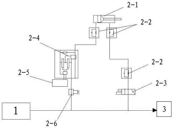
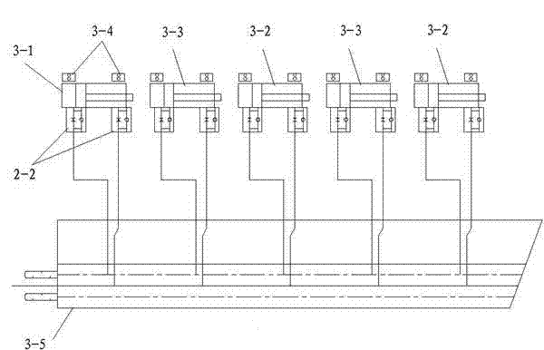
[0022] Example 1: Such as figure 1 , 2 A pneumatic control system of a bearing life testing machine shown in and 3, the pneumatic control system includes an air supply system 1 and an air assembly, and the air assembly includes a pneumatic system 2 of the transmission device and a temperature control box pneumatic System 3, the pneumatic system 2 of the transmission device includes a force cylinder 2-1, a pressure sensor 2-5 and a precision pressure reducing valve 2-6, and the pressure sensor 2-5 is connected to the On the force cylinder 2-1, a precision pressure relief valve 2-6 is provided on the connecting pipeline between the force cylinder 2-1 and the air supply system 1, and the temperature control box pneumatic system 3 includes a large cover Cylinder 3-1, two compact cylinders 3-3 and two guide cylinders 3-2, the five cylinders are connected in parallel on the air supply system through the valve guide structure 3-5.

[0023] The working pressure of the air circuit ...

Embodiment 2

[0025] Example 2: Such as image 3 As shown, the pneumatic system 3 of the temperature control box is installed on the temperature control box 4, the two compact cylinders 3-3 are installed on the upper part 4-3 of the temperature control box, and the two guide cylinders 3-2 are installed At the bottom 4-2 of the temperature control box, the large uncovered cylinder 3-1 is installed on the back 4-1 of the temperature control box. Different cylinders control the opening and closing of the movable doors at different positions on the temperature control box, and the device has a high degree of automation. , Simple and convenient operation, the stroke of each cylinder of the temperature control box pneumatic system 3 according to the present invention is controlled by the magnetic switches 3-4 located at both ends of the cylinder.

Embodiment 3

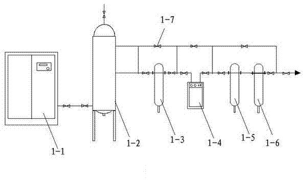
[0026] Example 3: Such as figure 1 As shown, the air supply system 1 is connected to the air storage tank 1-2, the main pipeline dust filter 1-3, and the refrigerated drying box 1-4 in sequence by the air compressor 1-1 through the pipeline and the valve 1-7. , the main line oil-water filter 1-5 and the high-efficiency degreasing filter 1-6 are connected to the air-consuming components through the high-efficiency degreasing filter 1-6.


PUM


Abstract

The invention discloses a pneumatic control system of a bearing service life tester. The pneumatic control system comprises a gas supplying system and a gas using assembly. The gas using assembly comprises a pneumatic system of a transmission device and a temperature control cabinet pneumatic system. The pneumatic system of the transmission device comprises a force exerting air cylinder, a pressure sensor and a precise reducing valve. The pressure sensor is connected to the force exerting air cylinder through a proportional valve. The precise reducing valve is arranged on a connecting pipeline of the force exerting air cylinder and the gas supplying system. The temperature control cabinet pneumatic system comprises a large uncovering air cylinder, two compact air cylinders and two guiding air cylinders, and the five air cylinders are connected to the gas supplying system in parallel through a valve guiding structure. The air cylinder structures of multiple pneumatic devices in the whole set of tester are controlled in an integrated mode through a set of pneumatic control systems, the automation degree of the pneumatic control system is high, operation is easy and convenient, the control pressure of a gas channel is stable, the testing precision of the tester is improved, the using cost of the instrument is saved, and control is convenient to conduct.

Description

technical field [0001] The invention relates to the structural field of a bearing life testing machine, in particular to a pneumatic control system of a bearing life testing machine. Background technique [0002] The new type of bearing life testing machine adopts mechanical, electrical and pneumatic comprehensive control to complete various testing functions of the equipment, among which pneumatic control is an important part of the machine, and its main functions are: 1) The test bearing installed on the testing machine works The temperature requirement is 120±5°C. In order to meet this requirement, the testing machine is equipped with a thermostat with multiple heating pipes to heat it up. The thermostat must be sealed, kept warm and dissipated. For this reason, two compact cylinders are installed on the upper part of the thermostat; two guide cylinders are installed on the bottom of the thermostat, and their function is to open the movable cover when the thermostat excee...

Claims


Application Information

Patent Timeline
Patent Type & Authority Applications(China)
IPC IPC(8): F15B11/16F15B21/04F15B13/06
Inventor 张辅忠
Owner NINGBO ZHENHAI SILVER BALL BEARING CO LTD
Why Eureka
Try Eureka