Self-centering friction drive lime rotary kiln

A lime rotary kiln and friction transmission technology, applied in the direction of rotary drum furnace, furnace, lighting and heating equipment, etc., can solve the problems of reduced service life of supporting wheels and rolling rings, excessive driving power consumption, increased maintenance costs, etc., to achieve The effect of reducing parts, reducing investment costs, and reducing maintenance costs

Active Publication Date: 2015-03-04
ACRE COKING & REFRACTORY ENG CONSULTING CORP DALIAN MCC
View PDF5 Cites 0 Cited by
  • Summary
  • Abstract
  • Description
  • Claims
  • Application Information

AI Technical Summary

Problems solved by technology

However, when the refractory material in the kiln is damaged, the temperature change of each part in the kiln can directly affect the theoretical value of this calculation, and then affect the effect of artificial adjustment.
The main impacts caused by the misalignment between the axis determined by the supporting wheel group and the axis of the kiln shell are: first, the kiln operation requires more force, resulting in excessive consumption of driving power and increased operating costs of the kiln; There is no longer linear contact between the rings, and the service life of the supporting roller and the rolling ring is reduced. Once maintenance is required, the kiln cooling will cause great damage to the refractory in the kiln, which increases the maintenance cost of the kiln.

Method used


Image

  • Self-centering friction drive lime rotary kiln
  • Self-centering friction drive lime rotary kiln
  • Self-centering friction drive lime rotary kiln

Examples


Embodiment Construction

[0019] Describe the concrete content of the present invention in detail below in conjunction with accompanying drawing:

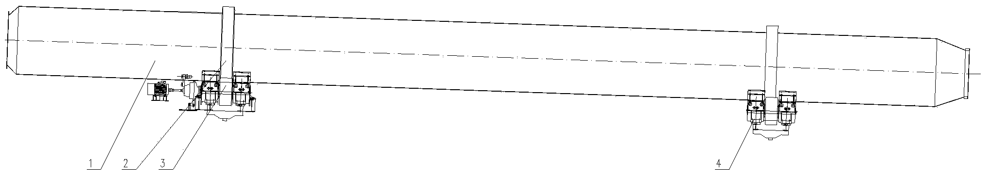
[0020] See figure 1 , is a structural schematic diagram of an embodiment of the self-adjusting friction transmission lime rotary kiln of the present invention, including the active supporting roller group 3, the driven supporting roller group 4, the kiln body 1 and the rolling ring 2, and the kiln body 1 is respectively equipped with active supporting rollers Group 3 and driven supporting wheel group 4, wherein the driving supporting wheel group 3 is matched with the rolling ring 4 on the feed side of the kiln body 1, and the driven supporting wheel group 4 is matched with the rolling ring 4 on the discharging side of the kiln body 1 Cooperate, the driving supporting wheel group 3 has a driving device, and the driven supporting wheel group 4 does not.

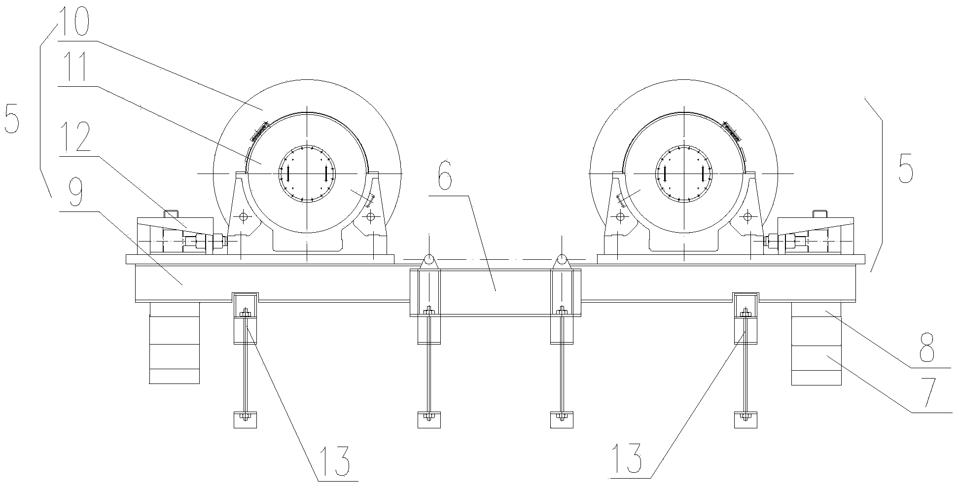
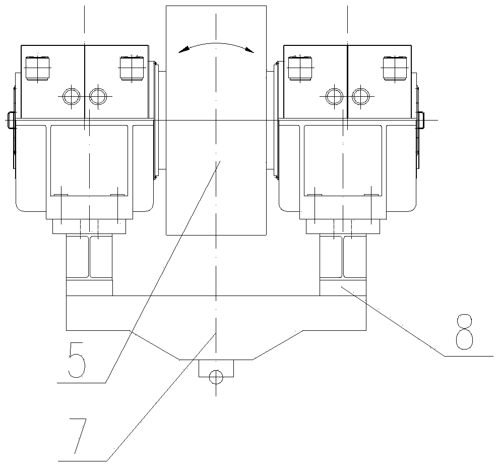
[0021] See figure 2 , image 3 , the driven roller group 4 includes two supporting roller devices 5 w...


PUM


Abstract

The invention relates to the field of rotary kilns for producing lime, in particular to a self-centering friction drive lime rotary kiln. The self-centering friction drive lime rotary kiln comprises a driving riding wheel set, a driven riding wheel set, a kiln body and rolling rings. The driving riding wheel set and the driven riding wheel set are arranged below the kiln body, wherein the driving riding wheel set is matched with the rolling ring on the feed side of the kiln body. The self-centering friction drive lime rotary kiln is characterized in that the driven riding wheel set comprises two riding wheel devices which are the same in structure and are symmetrically arranged, the opposite sides of the two riding wheel devices are hinged to the two ends of a central base plate respectively, a hinge beam is arranged below the bottom portions of the other sides of the two riding wheel devices, and an elastic rubber pad is arranged between the riding wheel devices and the hinge beam; when the driven riding wheel set makes contact with the other rolling ring, the central base plate is in a floating state. Compared with the prior art, the self-centering friction drive lime rotary kiln has the advantages that the centerlines of the riding wheel sets and the axes of the rolling rings of the kiln body are automatically centered, excessive abrasion to riding wheels and the rolling rings is avoided, the service life of the riding wheels and the service life of the rolling rings are prolonged, and maintenance cost, operation cost and investment cost of the kiln body are reduced.

Description

technical field [0001] The invention relates to the field of rotary kilns for producing lime, in particular to a self-adjusting middle friction transmission lime rotary kiln. Background technique [0002] Rotary kiln firing lime has a history of more than 300 years. Since the introduction of technology and equipment from Germany and the United States in the 1970s, vertical preheaters and vertical coolers have been widely promoted. At present, the vertical preheater and cooler technology are mostly used in the operating and newly built lime rotary kilns. The preheating of limestone and part of the decomposition reaction are carried out in the preheater, which further shortens the length of the rotary kiln. The length-to-diameter ratio of modern lime rotary kilns is all within 1:15. Therefore, the newly designed lime rotary kiln is supported by two sets of supporting rollers, which makes it possible to transmit torque by friction between the supporting rollers and the rolling...

Claims


Application Information

Patent Timeline
Patent Type & Authority Patents(China)
IPC IPC(8): F27B7/26
Inventor 徐大鹏夏敬山关世文白城杨耕桃
Owner ACRE COKING & REFRACTORY ENG CONSULTING CORP DALIAN MCC
Why Eureka
Try Eureka