Method for building lubricating oil film model after thermal coupling deformation of static pressure center frame

A thermal-mechanical coupling and lubricating oil film technology, applied in special data processing applications, instruments, electrical digital data processing, etc., to achieve optimal design, improve service life, and avoid lubrication failure

Inactive Publication Date: 2014-02-19
HARBIN UNIV OF SCI & TECH
View PDF4 Cites 6 Cited by
  • Summary
  • Abstract
  • Description
  • Claims
  • Application Information

AI Technical Summary

Problems solved by technology

[0004] This invention is to solve the problem that the current method of establishing the oil film model has a great influence on the machining accuracy of the workpiece and the working performance of the CNC lathe, and provides a method for establishing Method of lubricating oil film model after thermal-mechanical coupling deformation of hydrostatic steady rest

Method used


Image

  • Method for building lubricating oil film model after thermal coupling deformation of static pressure center frame
  • Method for building lubricating oil film model after thermal coupling deformation of static pressure center frame
  • Method for building lubricating oil film model after thermal coupling deformation of static pressure center frame

Examples


specific Embodiment approach 1

[0028] Specific implementation mode 1: Referring to each figure, a method for establishing a lubricating oil film model after thermomechanical coupling deformation of a hydrostatic steady rest in this embodiment is implemented in the following steps:

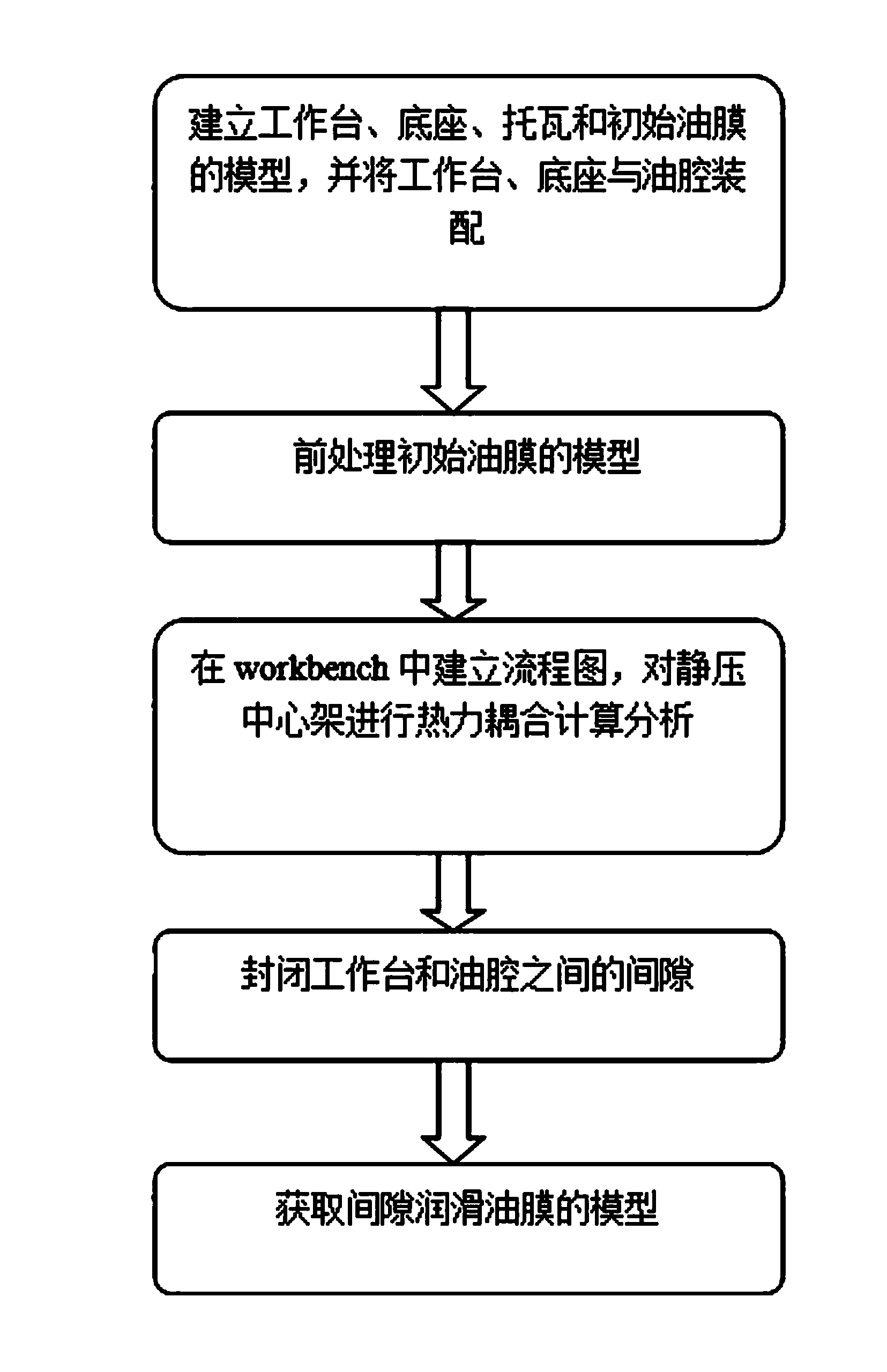
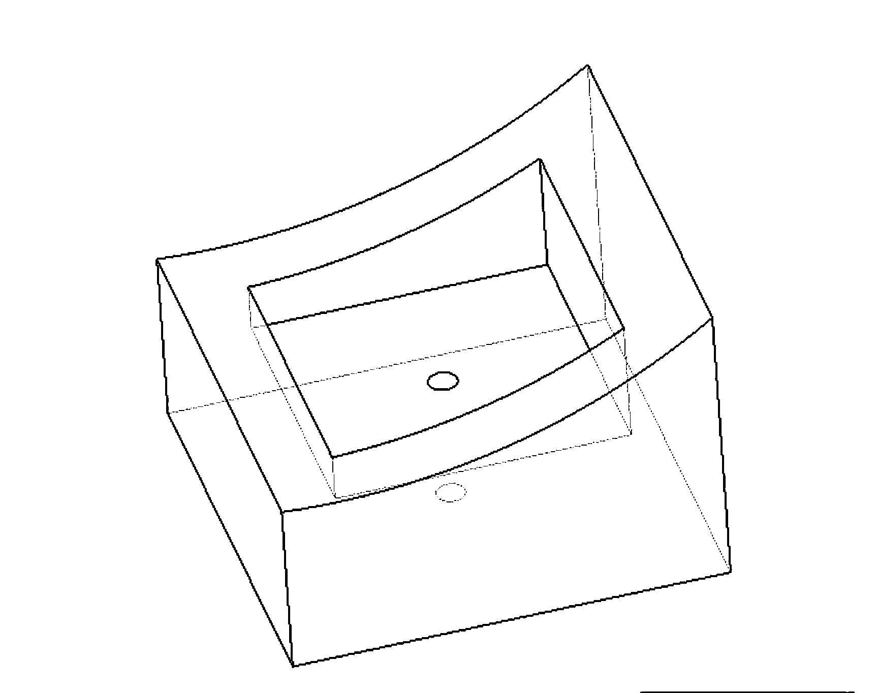
[0029] Step 1. According to the size structure of the test machine tool and the given initial oil film thickness, use UG to build the model of the workbench, base, support block and initial oil film, assemble the support block, workbench, base and oil chamber, and export it to zhengtizhuangpei. x_t and chushiyoumo.x_t files;

[0030] Step 2. Use CFD software to mesh the initial oil film to obtain a high-quality mesh, specify the boundary conditions of the fluid domain and output the chushiyoumo.fluent5 / 6mesh file, and import the chushiyoumo.fluent5 / 6mesh file into FLUENT to input or select the oil film inlet temperature T in Initial value, initial value of oil film fixed wall surface temperature, oil film inlet flow rate Q, ou...

specific Embodiment approach 2

[0034] Embodiment 2: The difference between this embodiment and Embodiment 1 is that in step 1, the workbench and the base are analyzed using a 1 / 4 model, and other steps and parameters are the same as Embodiment 1.

specific Embodiment approach 3

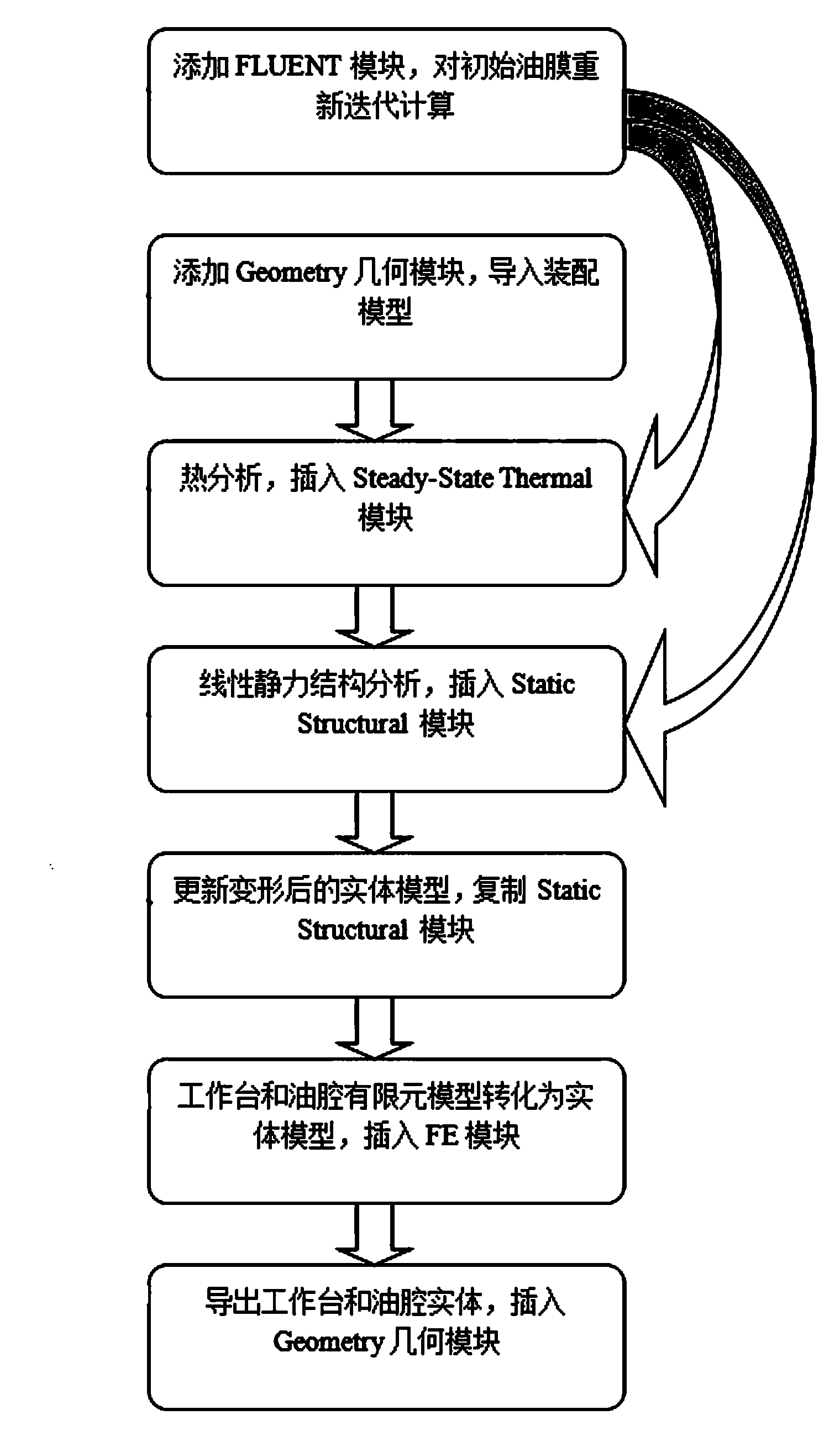
[0035] Specific embodiment three: the difference between this embodiment and specific embodiment one or two is that: Step 3 establishes a work flow chart in ANSYS WOERKBECH software, and performs thermomechanical coupling calculation and analysis on the static pressure steady rest as follows:

[0036] Step 3-1. Import the fluid analysis results, add the FLUENT module, import the chushiyoumo.cas file in step B into FLUENT and re-calculate iteratively;

[0037] Step 3-2. Import the assembly model, add the Geometry module, and import the zhengtizhuangpei.x_t file in step A;

[0038]Step 3-3, thermal analysis, insert the Steady-State Thermal module, and set the material properties of the workbench, base and oil chamber. Since only thermal analysis and linear structural analysis are required, it is only necessary to fill in the corresponding density in the material property window , Young's modulus, Poisson's ratio, and thermal conductivity; import the results of fluid analysis int...


PUM


Abstract

The invention relates to a method for building a lubricating oil film model, in particular to a method for building a lubricating oil film model after thermal coupling deformation of a static pressure center frame. The method aims to solve the problem that an existing method for building an oil film model has errors in workpiece efficiency and precision. The method comprises the steps that 1, a workbench, a base, supporting tiles on the two sides, a flat bottom deep oil chamber middle supporting tile and the model of an initial oil film are built, and the workbench, the base and the supporting tiles are assembled; 2, the model of the initial oil film is pretreated; 3, a flow diagram is built in the workbench, and thermal coupling computational analysis is carried out on the static pressure center frame; 4, the clearance between the workbench and an oil chamber is sealed; 5, the model of a clearance lubricating oil film is acquired. In actual application, the method is used for verifying the reasonable control over the flow of the lubricating oil of a large-size machine tool by the large-size machine tool so that it can be guaranteed that the large-size machine tool operates normally and safely, and the situations of dry friction, boundary lubrication and other lubrication failures are avoided.

Description

Technical field: [0001] The invention belongs to a method for establishing a lubricating oil film model, in particular to a method for establishing a lubricating oil film model after static pressure steady frame thermal coupling deformation. Background technique: [0002] Heavy-duty CNC machining plays a pivotal role in aerospace, heavy ships, steel, petroleum and other fields. The static pressure steady rest is a part of the heavy-duty CNC machine tool that supports the workpiece of the rotary shaft and enables it to be processed. It can bear loads in both vertical and horizontal directions at the same time. Compared with other supporting workpieces, it has the advantages of less frictional resistance, longer service life, lower requirements on rotational speed, and more stable vibrations, and can meet the requirements of high machining accuracy. In terms of the structural performance optimization of the hydrostatic center frame, previous studies are often limited to the...

Claims


Application Information

Patent Timeline
Patent Type & Authority Applications(China)
IPC IPC(8): G06F17/50
Inventor 于晓东周启慧王志强张艳芹刘丹付旭李欢欢谭力
Owner HARBIN UNIV OF SCI & TECH
Why Eureka
Try Eureka