Micro-channel radiator for dissipating heat of power electronic device

A technology for power electronic devices and heat sinks, applied in the field of micro-channel heat sinks, can solve problems such as unfavorable chip stable operation, uneven temperature distribution, and difficult realization of multiple inlets and outlets

Active Publication Date: 2014-02-19
SHANGHAI JIAO TONG UNIV
View PDF4 Cites 21 Cited by
  • Summary
  • Abstract
  • Description
  • Claims
  • Application Information

AI Technical Summary

Problems solved by technology

[0004] After searching the prior art, it was found that R.H.W.Pijnenburg et al. designed a parallel micro-channel cooling in silicon in the article "Integrated micro-channel cooling in silicon" published in Solid-State Device Research conference, 2004.ESSDERC2004.Proceeding of the34th European, 129-132. Multiple micro-channels are arranged, but there is still the problem of uneven temperature distribution. The position distribution of the inlet does not match the distribution of the heat source, and the uneven temperature distribution is not conducive to the stable operation of the chip.
[0005] Dorin Lelea designed a mu...

Method used


Image

  • Micro-channel radiator for dissipating heat of power electronic device
  • Micro-channel radiator for dissipating heat of power electronic device
  • Micro-channel radiator for dissipating heat of power electronic device

Examples


Embodiment 1

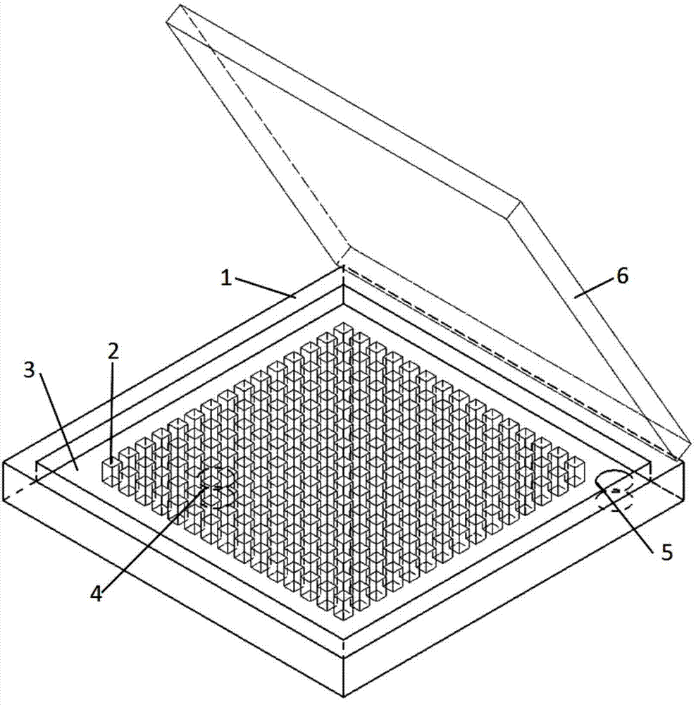
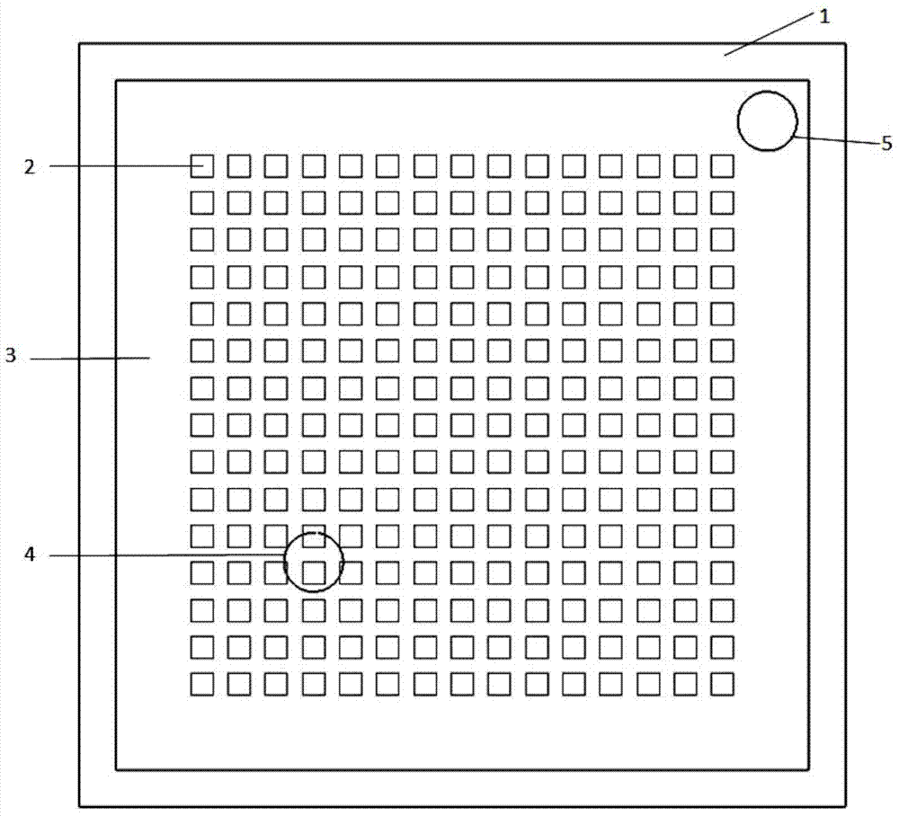
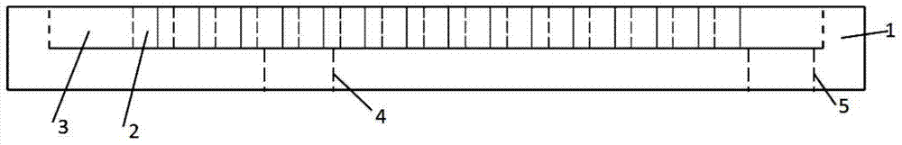
[0029] Such as figure 1 , figure 2 , image 3 As shown, the present embodiment provides a microchannel heat sink for heat dissipation of power electronic devices, including: heat sink outer wall 1, internal flow channel structure 2, heat dissipation working medium 3, working medium inlet 4, working medium outlet 5 and upper layer Cover plate 6, wherein: a flow guide channel is provided between the outer wall 1 of the radiator and the internal flow channel structure 2 to facilitate the outflow of the heat-dissipating working medium 3; the working medium outlet 5 is arranged at the One corner; the working fluid inlet 4 is arranged on the heat dissipation surface of the radiator and deviates from the center of the heat dissipation surface, and away from the side of the working medium outlet 5; the heat dissipation chip is connected to the upper cover plate 6, and its heat passes through the upper layer The cover plate 6 and the internal flow channel structure 2 connected there...

Embodiment 2

[0041] Such as Figure 4 , Figure 5 , Image 6As shown, this embodiment provides a microchannel radiator for heat dissipation of power electronic devices, including: radiator outer wall 1, internal flow channel structure 2, heat dissipation working medium 3, working medium inlet 4, working medium outlet 5 and upper layer The cover plate 6 and the connection of components are the same as those in Embodiment 1, and the position of the working fluid inlet 4 is slightly different.

[0042] In this embodiment, the internal flow channel structure 2 is a honeycomb cylindrical spoiler column, and a micro flow channel is formed between the spoiler columns; the radius of the spoiler column is 0.3mm, and the height is 0.5mm; the spoiler column The spacing between stream columns is 0.2mm.

[0043] In this embodiment, the hydraulic diameter of the working fluid outlet 5 is 0.7 mm.

[0044] In this embodiment, the hydraulic diameter of the working fluid inlet 4 is 0.7 mm.

[0045] In ...

Embodiment 3

[0053] Such as Figure 7 , Figure 8 , Figure 9 As shown, this embodiment provides a microchannel radiator for heat dissipation of power electronic devices, including: radiator outer wall 1, internal flow channel structure 2, heat dissipation working medium 3, working medium inlet 4, working medium outlet 5 and upper layer The cover plate 6 and the connection of components are the same as those in Embodiment 1.

[0054] In this embodiment, the internal channel structure 2 is a honeycomb cuboid spoiler column, and micro-channels are formed between the spoiler columns; the narrow side of the spoiler column is 0.1mm wide and 0.5mm high; The spacing between spoiler columns is 0.3mm or 0.5mm.

[0055] In this embodiment, the hydraulic diameter of the working fluid outlet 5 is 0.8 mm.

[0056] In this embodiment, the hydraulic diameter of the working fluid inlet 4 is 0.8 mm.

[0057] In this embodiment, the width of the drainage channel is 1mm.

[0058] In this embodiment, th...


PUM

PropertyMeasurementUnit
Hydraulic diameteraaaaaaaaaa
Thicknessaaaaaaaaaa
Radiusaaaaaaaaaa

Abstract

The invention provides a micro-channel radiator for dissipating heat of a power electronic device. The micro-channel radiator comprises an upper-layer cover board, a radiator outer wall, an internal flow channel structure, a heat dissipation working medium, a working medium inlet and a working medium outlet. The upper-layer cover board is connected a chip with heat to be dissipated, and the upper-layer cover board is in contact with the internal flow channel structure. Heat of the chip with heat to be dissipated is transmitted into the heat dissipation working medium through the upper-layer cover board and the internal flow channel structure and brought out through the heat dissipation working medium. The working medium outlet is formed in the inner side of the outer wall of the radiator. The working medium inlet is formed in the side, away from the position of the working medium outlet, of an eccentric position. According to the micro-channel radiator for dissipating heat of the power electronic device, the fresh heat dissipation working medium which has the lowest temperature is led into the radiator from the center area of a heat dissipation face which has the highest temperature, improvement of the heat exchange efficiency of the radiator is facilitated, the micro-channel radiator is constructed with selected metal materials with a high heat conduction rate, the heat dissipation efficiency is high, in addition, the manufacturing technology is mature, and the micro-channel radiator is easy to achieve.

Description

technical field [0001] The invention relates to the fields of power device heat dissipation technology and high-efficiency heat exchange technology, in particular to a microchannel heat sink for power electronic device heat dissipation. Background technique [0002] With the rapid development of technology, the high density and miniaturization of electronic devices has become a trend. Especially for high-power devices, heat dissipation has become an urgent problem to be solved. Due to the miniaturization of devices, the miniaturization of radiators has also become a trend. Microchannels are favored due to their high surface-to-volume ratio and excellent heat dissipation properties. [0003] Existing microchannel heat sinks generally use one side to lead in and the other side to lead out in a circular way. There is a common law that the temperature distribution of the chip rises gradually along the flow direction of the cooling medium, which does not correspond to the distrib...

Claims


Application Information

Patent Timeline
IPC IPC(8): H01L23/367
Inventor 丁桂甫赵军红王桂莲王艳
Owner SHANGHAI JIAO TONG UNIV
Why Eureka
Try Eureka