
A method and system for loading, unloading and cutting a longitudinal metal plate

A cutting system and cutting method technology, applied in metal processing, metal processing equipment, welding/cutting auxiliary equipment, etc., can solve the problems of complex control design of handling and stacking units, tight and cramped factory layout, etc., to ensure the quality of processing and installation , convenient working method and compact system layout

Active Publication Date: 2015-08-26
BAOSHAN IRON & STEEL CO LTD +1
View PDF8 Cites 2 Cited by
  • Summary
  • Abstract
  • Description
  • Claims
  • Application Information

AI Technical Summary

Problems solved by technology

In addition, each fast table includes a cutting position and two group material loading and sheet material unloading positions, and there are correspondingly two group material trolley stacks and sheet material trolley stacks. The stacking unit control design is more complicated
This method occupies the horizontal length of the factory, which makes the layout of the factory area quite tense and cramped

Method used


Image

  • A method and system for loading, unloading and cutting a longitudinal metal plate
  • A method and system for loading, unloading and cutting a longitudinal metal plate
  • A method and system for loading, unloading and cutting a longitudinal metal plate

Examples


Embodiment Construction

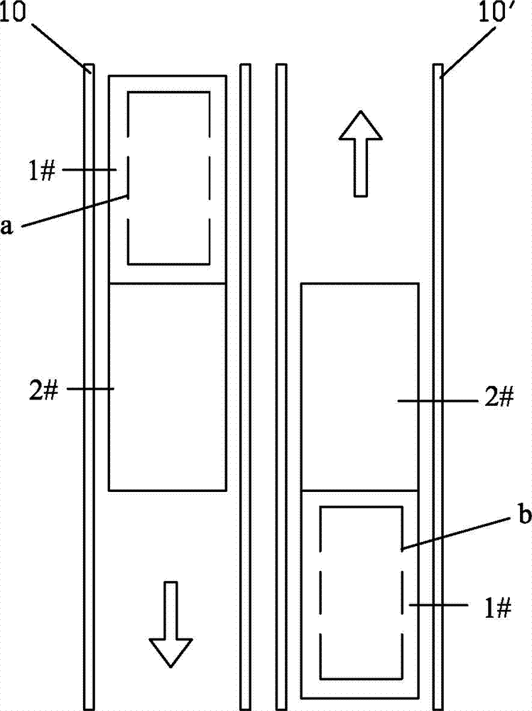
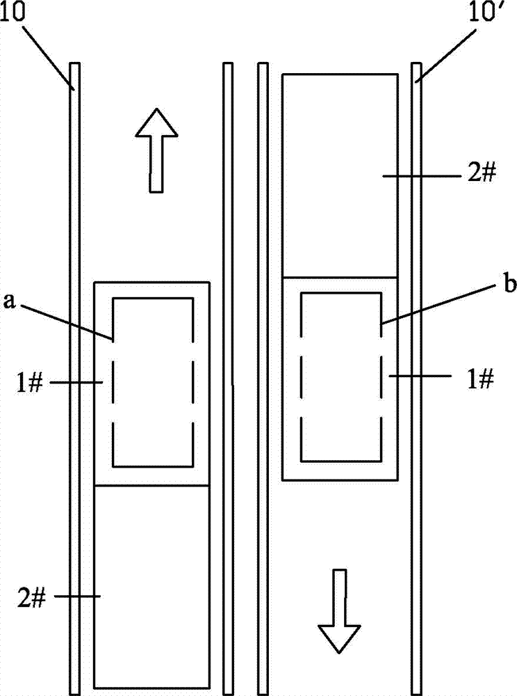
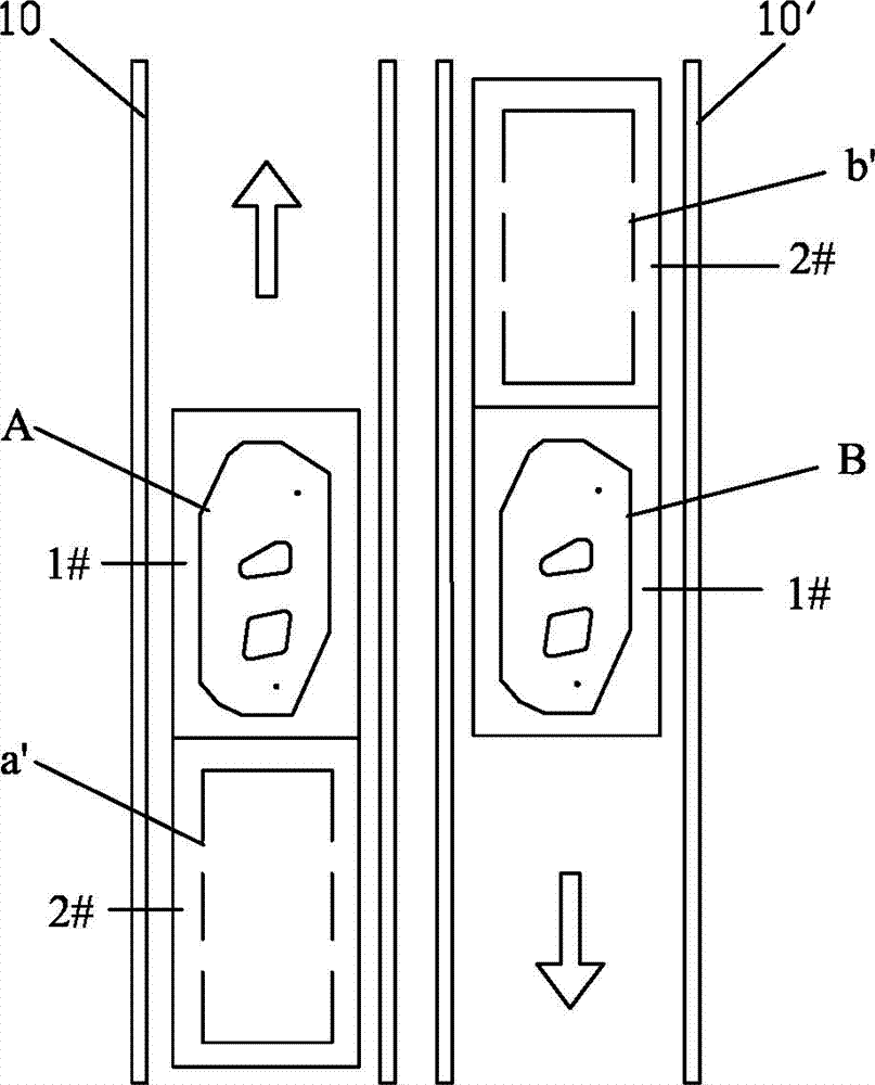
[0025] refer to figure 1 , figure 2 , a metal plate cutting system of the present invention adopts two vertically moving loading and unloading and cutting operation lines A and B arranged in parallel, and each operation line A and B respectively include group material feeding positions 1, 1', cutting workers Positions 2, 2', sheet unloading positions 3, 3', two handling and stacking robots 4, 4' and corresponding external axes 41, 41' set between the two operation lines; two operation lines A , The setting direction of group B material loading level 1, 1' is opposite; said group material loading level 1, 1', sheet material lowering level 3, 3' are respectively set group material trolley 5, 5', and sheet material trolley 6 , 6' and corresponding guide rails 7, 7', 8, 8'; cutting stations 2, 2' are equipped with at least one laser generator and two laser cutting heads 9, 9' and moving group materials, sheet materials in and out The mobile fast table 10, 10' in the cutting are...


PUM

PropertyMeasurementUnit
lengthaaaaaaaaaa

Abstract

A longitudinal metal plate loading, unloading and cutting method and system, which adopts two longitudinal moving loading and unloading and cutting operation lines set up in parallel. Each operation line includes an assembly loading position, a cutting station, and a sheet material unloading position. And a handling and stacking robot is located between the two operating lines; the two operating lines have opposite directions for assembling and loading materials; the assembly loading position and the sheet material discharging position are equipped with assembly trolleys, sheet trolleys and guide rails; cutting The workstation is equipped with at least two laser cutting heads and a mobile fast table; the mobile fast table moves longitudinally, feeds in and out of materials in two directions, and is equipped with two waiting positions and one cutting position; the external axes of the handling and stacking robot span the respective working lines. The assembly material loading position and the corresponding moving fast table and one waiting position are also across the sheet material lowering position of the opposite operating line and the corresponding moving fast table and another waiting position; each cutting station is equipped with A scrap conveyor system. The invention can effectively improve the cutting operation rhythm and output, and at the same time the system layout is more reasonable.

Description

technical field [0001] The invention relates to the field of metal processing, in particular to a method and system for loading, unloading and cutting metal plates used in the technical field of automobile manufacturing. Background technique [0002] Laser technology is already a mature commercial technology in the field of material cutting and processing. At the same time, with the development of laser generators, it has brought faster processing speed, more flexible application methods, and the emergence of automatic loading and unloading, Demand for high-paced continuous production. With the development of robots and their control technologies, the handling and loading and unloading systems developed based on robot automation control have become more and more perfect. In this context, the realization of an integrated system for loading and unloading operations and cutting can be greatly improved Meet the processing needs of customers. For example, the published patent C...

Claims


Application Information

Patent Timeline
Patent Type & Authority Patents(China)
IPC IPC(8): B23K26/38B23K26/70
CPCB23K26/702B23K26/16B23K26/38B23K2101/006B23K2101/16B23K26/0846B23K37/00B23K37/0235B23K26/40B23K2101/18B23K2103/04B23K26/0884
Inventor 杨赛丹乔俊良金文海潘胜波吴瑞珉金成国王玉明
Owner BAOSHAN IRON & STEEL CO LTD
Learn More