A self-adaptive clamping and positioning device for blades

A clamping positioning and self-adaptive technology, applied in positioning devices, attachment devices, clamping, etc., can solve problems such as positioning errors, surface processing errors, and large consumption of manpower and material resources, so as to reduce production costs and improve production efficiency , Guarantee the effect of machining accuracy

Inactive Publication Date: 2015-11-04
SHENYANG LIMING AERO-ENGINE GROUP CORPORATION
View PDF12 Cites 0 Cited by
  • Summary
  • Abstract
  • Description
  • Claims
  • Application Information

AI Technical Summary

Problems solved by technology

For the processing of the hole system of the blade body, in order to ensure the processing accuracy of the blade, technicians often use EDM machine tools for processing, because EDM has the advantages of no cutting force and good surface processing quality, but EDM is performed on the blade Before processing, the blade needs to be clamped and positioned. The positioning method used is to use the blade tenon as the positioning reference. The actual situation is that the blade tenon usually has a certain surface processing error, so the blade tenon with the error is used as the reference for positioning. The blade will have a greater positioning error, so that the machining accuracy of the blade after EDM is extremely low, and the scrap rate of the blade is very high
The currently used blade clamping and positioning devices are all rigid constraint structures. Under rigid constraint conditions, it is difficult to eliminate the processing error of the blade tenon profile. In order to ensure the smooth progress of the subsequent processing of the blade, the blade tenon can only be re-corrected. The process will consume a lot of manpower and material resources, and the production efficiency is low, thereby increasing the production cost

Method used


Image

  • A self-adaptive clamping and positioning device for blades
  • A self-adaptive clamping and positioning device for blades
  • A self-adaptive clamping and positioning device for blades

Examples


Embodiment Construction

[0024] The present invention will be further described in detail below in conjunction with the accompanying drawings and specific embodiments.

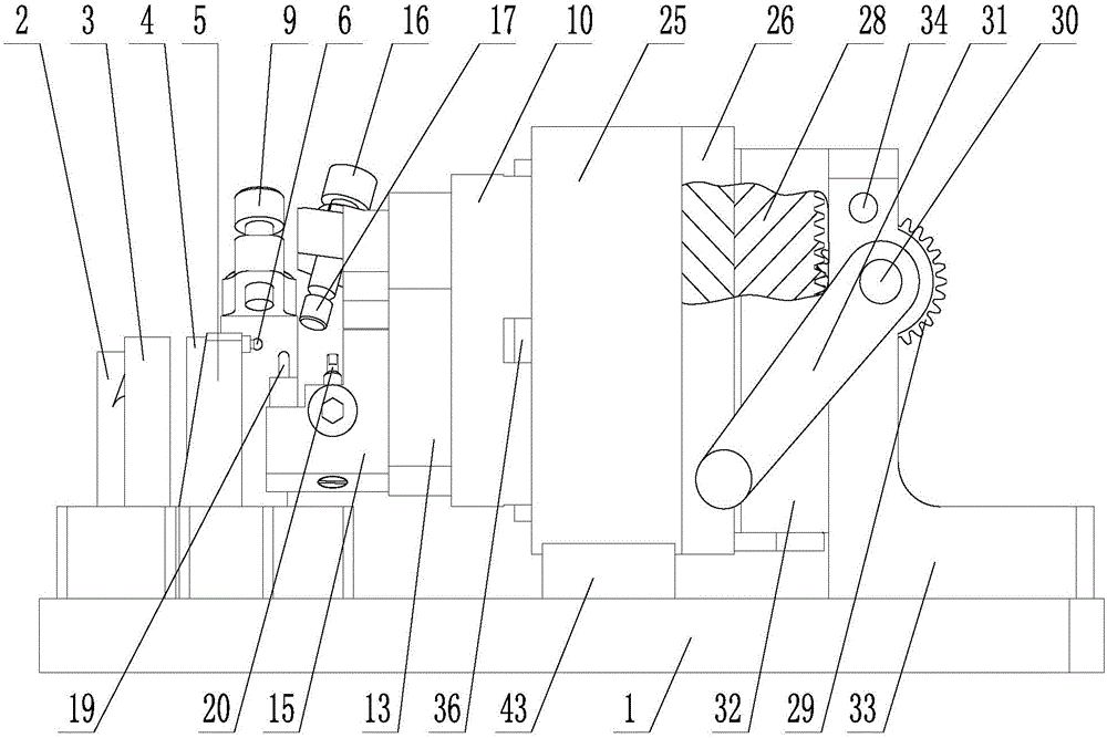
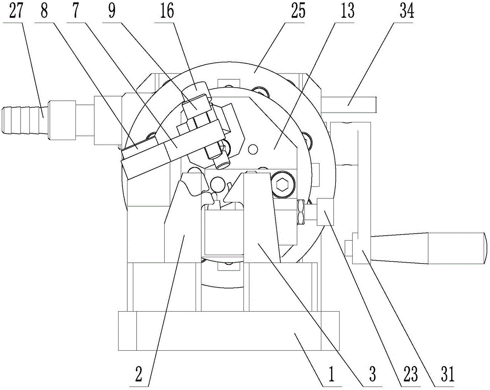
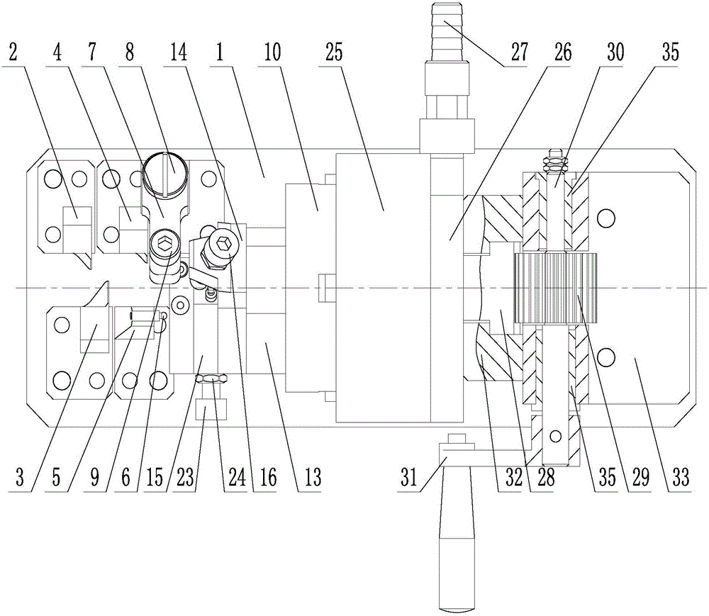
[0025] Such as figure 1 , 2 , 3, 4, 5, and 6, a self-adaptive clamping and positioning device for a blade, including a base 1, a blade body positioning part, a blade tenon clamping and positioning part, a positioning transfer part, a processing transfer part and positioning adjustment part;

[0026] The airfoil positioning part includes a first airfoil positioning seat 2, a second airfoil positioning seat 3, a third airfoil positioning seat 4 and a blade edge plate positioning seat 5. The first airfoil positioning seat 2, the second airfoil positioning seat The airfoil positioning seat 3 and the third airfoil positioning seat 4 are fixed on the base 1, and the upper profiles of the first airfoil positioning seat 2, the second airfoil positioning seat 3 and the third airfoil positioning seat 4 are respectively Corresponding to the a...


PUM


Abstract

The invention belongs to the technical field of aeroengine part manufacturing, and relates to a self-adaptive blade clamping and positioning device which comprises a base, a blade body positioning portion, a blade tenon clamping and positioning portion, a positioning adapter portion, a machining adapter portion and a positioning adjustment portion. The blade body positioning portion comprises blade body positioning seats and a blade margin plate positioning seat and is used for positioning a blade body. The blade tenon clamping and positioning portion which is demountable comprises a fast mounting seat, a compression bolt, ejection pins and an ejection rod, is used for clamping a positioned blade tenon, and can be quickly connected with the positioning adapter portion to complete blade clamping and positioning. Compared with the prior art, the self-adaptive blade clamping and positioning device has the advantages that a manner taking the blade tenon as a positioning reference is abandoned, a blade body profile of the blade is taken as the positioning reference, the blade tenon can be clamped self-adaptively in the blade positioning process, influences of blade tenon profile machining errors on blade machining accuracy are eliminated, blade machining accuracy is guaranteed, production efficiency is improved, and production cost is lowered.

Description

technical field [0001] The invention belongs to the technical field of manufacturing aero-engine components, in particular to a self-adaptive clamping and positioning device for blades. Background technique [0002] As a typical turbomachinery, the blades in the aero-engine usually have complex blade shapes and space angles, making machining difficult, and the machining accuracy of the blades directly affects the overall performance of the aero-engine. For the processing of the hole system of the blade body, in order to ensure the processing accuracy of the blade, technicians often use EDM machine tools for processing, because EDM has the advantages of no cutting force and good surface processing quality, but EDM is performed on the blade Before processing, the blade needs to be clamped and positioned. The positioning method used is to use the blade tenon as the positioning reference. The actual situation is that the blade tenon usually has a certain surface processing error...

Claims


Application Information

Patent Timeline
Patent Type & Authority Patents(China)
IPC IPC(8): B23Q3/08B23H11/00
CPCB23H11/003
Inventor 陈宏海彭会文曾庆国王积全祖峰
Owner SHENYANG LIMING AERO-ENGINE GROUP CORPORATION
Why Eureka
Try Eureka