
Local slope type reduction ironmaking furnace and process

A slope-type, iron-making furnace technology, applied in the reduction iron-making furnace and the iron-making process, the reduction-iron-making process, the integrated reduction iron-making furnace field, can solve the problem of wall hanging, uneven reaction of furnace materials and low production efficiency And other issues

Inactive Publication Date: 2014-02-26
SHANDONG UNIV +1
View PDF8 Cites 2 Cited by
  • Summary
  • Abstract
  • Description
  • Claims
  • Application Information

AI Technical Summary

Problems solved by technology

[0004] The object of the present invention is to improve the existing defects of the above-mentioned iron-making furnace, and provide a partial slope reduction iron-making furnace. Wall, low production efficiency and other problems, more conducive to large-scale production

Method used


Image

  • Local slope type reduction ironmaking furnace and process
  • Local slope type reduction ironmaking furnace and process
  • Local slope type reduction ironmaking furnace and process

Examples


Embodiment 1

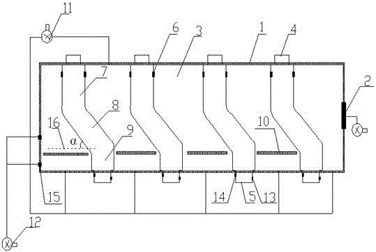
[0058] Such as figure 1 The partial slope reduction ironmaking furnace shown (referred to as the reduction ironmaking furnace, the same below) includes a closed furnace body 1, and an exhaust port 2 for exhausting gas is provided on the furnace body. The exhaust port is located in the middle of the furnace body, close to The position of the last reduction chamber is equipped with an induced draft fan and other devices on the exhaust port to discharge the carbon dioxide in the furnace body. Four reduction chambers are arranged in sequence in the furnace body. Of course, the number of reduction chambers can be freely allocated in practical applications. Here only Taking a reduction furnace with four reduction chambers as an example to illustrate its structure, the four reduction chambers are independent. The top of the reduction chamber is provided with a feed port 4, and the bottom is provided with a discharge port 5. Both the feed port and the discharge port are located outsi...

Embodiment 2

[0062] The structure of the local slope reduction ironmaking furnace of the present invention can be adjusted appropriately on the basis of Embodiment 1, for example, the number of air extraction device and air supply device can be one, and one can also be arranged at each cavity, When only one is used, the air extraction device and the air delivery device are preferably installed at a position away from the exhaust port.

Embodiment 3

[0064] The structure of the local slope-type reduction ironmaking furnace of the present invention can be appropriately adjusted on the basis of Embodiment 1, for example, an air inlet can be arranged at the position above the baffle and below the baffle at each cavity.


PUM

PropertyMeasurementUnit
particle sizeaaaaaaaaaa

Abstract

The invention discloses a local slope type reduction ironmaking furnace and process. A reduction chamber of the ironmaking furnace is in a local slope design, the reduction chamber orderly comprises a pre-reduction area, a transition area and a fusion area from top to bottom; the pre-reduction area and the fusion area are vertically arranged in a furnace body, the transition area is inclined and has a fixed angle with a furnace body horizontal line; a heat-resisting baffle is arranged in each cavity, the heat-resisting baffle is fixed on the furnace body, and a gap is between the heat-resisting baffle and the reduction chamber. The ironmaking furnace can be flexibly regulated between the performing fusion reduction and direct reduction and can realize the recycling of the carbon monoxide gas, the cost is greatly lowered; the ironmaking furnace used for ironmaking can realize continuous production, stable operation, uniform material heating and complete reaction; the situation that material are attached to the furnace wall can be effectively controlled, and the wastewater treatment problem is avoided; the ironmaking furnace is friendly to the environment and meets the demands of environmental protection and cleaner production.

Description

technical field [0001] The invention relates to a reduction ironmaking furnace and ironmaking process, in particular to an integrated reduction ironmaking furnace with a partial slope structure in the reduction chamber and a reduction ironmaking process using the ironmaking furnace, which belongs to iron ore smelting technology field. Background technique [0002] At present, the products refined from iron ore are mainly molten iron and sponge iron. The processes for refining iron ore into molten iron mainly include blast furnace method, direct reduction method, smelting reduction method, and plasma method. The smelting reduction method has attracted the attention of experts at home and abroad because of its advantages such as less environmental pollution, less investment, and short process. It is a major topic in the field of non-blast furnace ironmaking at present. At present, the production process of sponge iron is mainly the rotary hearth furnace method. The rotary h...

Claims


Application Information

Patent Timeline
Patent Type & Authority Applications(China)
IPC IPC(8): C21B11/00C21B13/00
Inventor 胡丽娜李增元
Owner SHANDONG UNIV
Learn More