
Method for realizing high frequency channel test and signal reset

A high-frequency channel and signal technology, applied in the field of relay protection and automatic device inspection, can solve the problems of frequent abnormality of high-frequency channels, inability to achieve manual reset, troublesome maintenance personnel, etc., to achieve easy operation and easy grasp, and ensure safe and stable operation. , The effect of avoiding the waste of human, material and financial resources

Inactive Publication Date: 2014-02-26
STATE GRID CORP OF CHINA +1
View PDF6 Cites 3 Cited by
  • Summary
  • Abstract
  • Description
  • Claims
  • Application Information

AI Technical Summary

Problems solved by technology

However, with the continuous development of the State Grid Corporation of China's "three sets and five major systems", the pattern of integrated operation and maintenance and regulation and control has gradually formed, and 220kV unattended stations have appeared one after another. Like the duty station, the method of relying only on the inspectors of the centralized control center to rush to the substation for manual testing is a waste of manpower and material resources, which can no longer meet the requirements
In addition, when the alarm margin of the transceiver is not large, the high-frequency channel will be frequently abnormal due to the weather, and the "high-frequency channel abnormality" and "transceiver 3db alarm" signals will be reported. With the disappearance of the abnormal fluctuation, " The high-frequency channel abnormal" signal disappears automatically, but the "transceiver 3db alarm" signal needs to be reset manually, and the 220kV unattended station cannot realize timely manual reset. If it is not reset in time, when the transceiver operates again next time, it will be There will be such and such questions, which will cause unnecessary trouble to the maintenance personnel.

Method used


Image

  • Method for realizing high frequency channel test and signal reset
  • Method for realizing high frequency channel test and signal reset

Examples


Embodiment Construction

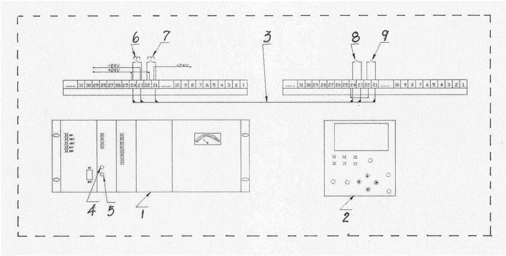
[0008] attached figure 1 It is a logical wiring schematic diagram of a specific embodiment of the present invention: firstly, a secondary cable 3 is laid between the high-frequency transceiver 1 with the high-frequency channel interval in the substation and the corresponding interval measurement and control device 2, and the The high-frequency channel test button contact 6 of the interval high-frequency transceiver channel test button 4 and the high-frequency transceiver reset button contact 7 of the high-frequency transceiver signal reset button 5 lead to the corresponding interval measurement and control device 2, and are connected with the measurement and control device The remote control contacts 8 and 9 of 2 correspond one-to-one, that is, one remote control contact 8 corresponds to the high-frequency channel test button contact 6, and one remote control contact 9 corresponds to the high-frequency transceiver reset button contact 7.

[0009] The operation steps of the pre...


PUM


Abstract

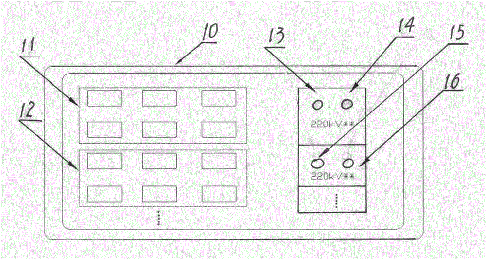
A method for realizing high frequency channel test and signal reset is provided. The method comprises the following steps that: channel test contacts and signal reset contacts of a high-frequency transceiver with a high-frequency channel interval in each substation are led to a detection control device of a corresponding interval and are corresponding to remote control contacts of the detection control device; an interface is constructed in a scheduling-end monitoring machine operating system, one channel test button and one signal reset button are defined corresponding to each interval in the interface; in the interface of the scheduling-end monitoring machine operating system, the validity of access is checked according to the channel test buttons of the interface; high-frequency channel abnormality is simulated, and the high-frequency transceiver is made to act, and then, the abnormality is made to vanish, and then, the signal reset button is pressed, and the validity of access is checked; and the high frequency channel test and signal reset of corresponding intervals can be realized through remote operation. The method is advantageous in simplicity, intuitiveness in vision, convenient operation and easiness in grasp, and can assist in improving work efficiency, avoiding the waste of human material and financial resources, and ensuring safe and stable operation of a power grid.

Description

technical field [0001] The invention relates to a method for realizing high-frequency channel test and signal recovery in a power system through a remote place, and belongs to the field of relay protection and automatic device inspection. Background technique [0002] With the increase of the scale of the power grid and the improvement of the stability requirements of the power grid, the longitudinal protection has become the main protection of the 220kV and above voltage level line protection. Power carrier high-frequency channel (hereinafter referred to as high-frequency channel) is one of the main channels of line longitudinal protection (this line longitudinal protection is also called line high-frequency protection), and the high-frequency channel includes transmission lines and high-frequency wave traps , coupling capacitor, combined filter, high-frequency cable, protection gap, grounding knife switch, high-frequency transceiver, relay protection device, any component...

Claims


Application Information

Patent Timeline
IPC IPC(8): G01R31/00
Inventor 高世伟朱辉蒋雷魏志海孙浩然孙海玉宋浩铨张楠
Owner STATE GRID CORP OF CHINA
Learn More