Thin-substrate phase amplitude correction quari-yagi difference beam planar horn antenna

A technology of horn antenna and amplitude correction, which is applied in waveguide horns, antennas, antenna unit combinations with different polarization directions, etc., can solve problems such as low gain of horn antennas, uneven distribution of aperture electric field intensity amplitude, zero depth of differential beam antennas, etc. , to achieve the effects of correcting phase and amplitude inconsistencies, excellent radiation performance, and low feed loss

Inactive Publication Date: 2014-02-26
SOUTHEAST UNIV
View PDF3 Cites 3 Cited by
  • Summary
  • Abstract
  • Description
  • Claims
  • Application Information

AI Technical Summary

Problems solved by technology

In addition, the gain of the traditional substrate-integrated waveguide planar horn antenna is relatively low. The reason is that due to the continuous opening of the horn mouth, the phase is not synchronized when the electromagnetic wave propagates to the horn aperture surface, and the amplitude distribution of the aperture electric field intensity is not uniform. The radiation directivity and gain are reduced, making the zero depth of the formed differe

Method used


Image

  • Thin-substrate phase amplitude correction quari-yagi difference beam planar horn antenna

Examples


Embodiment Construction

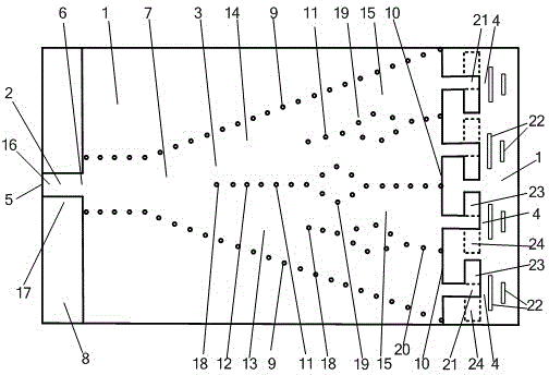
[0026] The embodiment adopted in the present invention is: the thin substrate phase amplitude correction quasi-Yagi difference beam planar horn antenna includes a microstrip feeder 2 arranged on a dielectric substrate 1, a substrate integrated horn antenna 3 and a plurality of quasi-Yagi antennas 4; The first port 5 of the microstrip feeder 2 is the input and output port of the antenna, and the second port 6 of the microstrip feeder 2 is connected to the substrate integrated horn antenna 3; The first metal plane 7, the second metal plane 8 located on the other side of the dielectric substrate 1, and two rows of metallized via hole horn sidewalls 9 passing through the dielectric substrate 1 to connect the first metal plane 7 and the second metal plane 8, basically The width between the two rows of metallized via hole horn side walls 9 of the chip integrated horn antenna 3 gradually increases to form a horn-shaped opening, and the end of the opening is the aperture surface 10 of ...


PUM


Abstract

The invention discloses a thin-substrate phase amplitude correction quari-yagi difference beam planar horn antenna, and relates to a horn antenna. The thin-substrate phase amplitude correction quari-yagi difference beam planar horn antenna comprises a micro-strip feeder (2), a horn antenna body (3) and quari-yagi antennas (4), wherein the micro-strip feeder (2), the horn antenna body (3) and the quari-yagi antennas (4) are arranged on a dielectric substrate (1), the horn antenna body (3) comprises a first metal plane (7), a second metal plane (8) and two metallization through hole horn side walls (9), the horn antenna body (3) is provided with metallization through an odd number of hole arrays (11), and an even number of dielectric-loaded waveguides (15), on an aperture surface (10) of the horn antenna body (3), the widths of the dielectric-loaded waveguides (15) are equal, the dielectric-loaded waveguides (15) are connected with the quari-yagi antennas (4) which comprise active oscillators (21) and passive oscillators (22), and a left-half antenna (13) and a right-half antenna (14) are arranged symmetrically. Electromagnetic waves can reach the quari-yagi antennas in an equal-amplitude and in-phase mode and then carry out radiation, and the direction of polarization of a radiation field is parallel to the dielectric substrate; according to the thin-substrate phase amplitude correction quari-yagi difference beam planar horn antenna, the thin substrate can be adopted, and the thin-substrate phase amplitude correction quari-yagi difference beam planar horn antenna is high in gain, large in zero drawdown, low in cost and compact in structure.

Description

technical field [0001] The invention relates to a horn antenna, in particular to a planar horn antenna with a thin substrate phase amplitude correction quasi-Yagi difference beam. Background technique [0002] Horn antennas are widely used in systems such as satellite communications, ground microwave links, and radio telescopes. However, the huge geometric size of the three-dimensional horn antenna restricts its application and development in planar circuits. In recent years, the proposal and development of substrate-integrated waveguide technology have greatly promoted the development of planar horn antennas. The substrate-integrated waveguide has the advantages of small size, light weight, easy integration and fabrication. The planar substrate-integrated waveguide horn antenna based on the planar substrate-integrated waveguide not only has the characteristics of the horn antenna, but also realizes the miniaturization and light weight of the horn antenna, and is easy to...

Claims


Application Information

Patent Timeline
IPC IPC(8): H01Q19/30H01Q21/24H01Q13/02H01Q1/38H01Q3/28H01Q3/30
Inventor 殷晓星赵洪新任刚
Owner SOUTHEAST UNIV
Why Eureka
Try Eureka