A pump light multi-pass transmission system and disk solid-state laser

A transmission system and pump light technology, applied in the laser field, can solve the problems of limited pump times, low system conversion efficiency, low pump light absorption efficiency, etc., to reduce thermal distortion, design difficulty, and pump spot distribution. uniform effect

Inactive Publication Date: 2015-12-30
HUAZHONG UNIV OF SCI & TECH +1
View PDF1 Cites 2 Cited by
  • Summary
  • Abstract
  • Description
  • Claims
  • Application Information

AI Technical Summary

Problems solved by technology

[0008] In view of the above defects or improvement needs of the prior art, the present invention provides a solid-state laser multi-pass transmission system based on a right-angle reflector and a conjugated double paraboloid reflector, the purpose of which is to disperse the distribution of the pump spot on the paraboloid mirror, Make it more uniform, reduce the unevenness and thermal distortion of the pump spot of the disc laser crystal caused by the deformation caused by the uneven distribution of the pump light on the parabolic surface, and improve the beam quality of the output light; on the other hand, this scheme On the basis of improving the uniform distribution of pump power, under the condition of the same parabolic caliber, by making full use of the parabolic mirror, the existing solution has limited pumping times, resulting in low absorption efficiency of pump light and low conversion efficiency of the system. lower issues, thereby improving the beam quality of the output laser

Method used


Image

  • A pump light multi-pass transmission system and disk solid-state laser
  • A pump light multi-pass transmission system and disk solid-state laser
  • A pump light multi-pass transmission system and disk solid-state laser

Examples


Embodiment 1

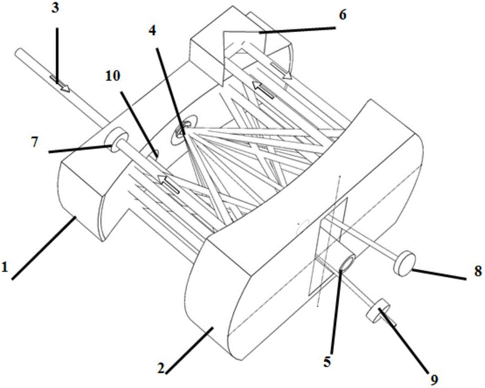
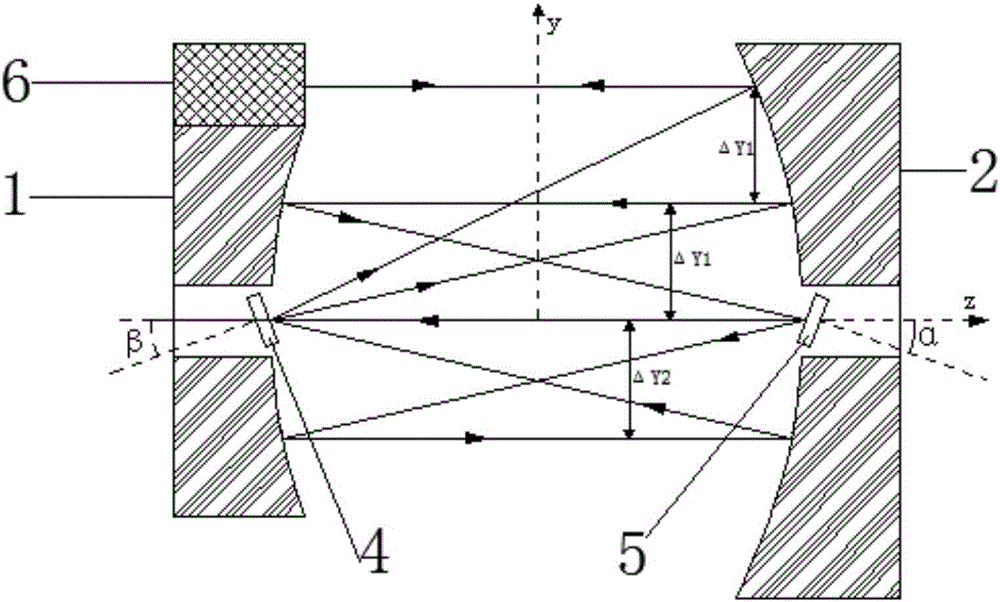
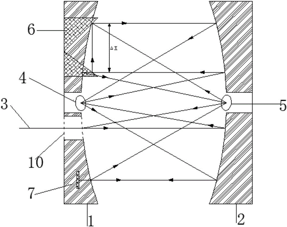
[0044] Pump light multi-pass transmission systems, such as figure 1 shown. The first parabolic mirror 1 and the second parabolic mirror 2 are placed in a conjugate, that is, the focus of the first parabolic mirror 1 is at the center of the second parabolic mirror 2, and the focus of the second parabolic mirror 2 is at the first at the center of the parabolic mirror 1. The first parabolic mirror is provided with a pump light incident hole 10 . The height of the first parabolic mirror 1 is lower than that of the second parabolic mirror 2 , and the height difference is used to place the right-angle total reflection mirror 6 and the pump light total reflection mirror 7 . The right-angle mirror 6 and the pump light total reflection mirror 7 are placed on both sides above the first parabolic mirror 1, and the right-angle surface of the right-angle mirror 6 faces the second parabolic mirror, which is used to realize the lateral shift of the incident light. 180 degree reflection. ...

Embodiment 2

[0051] Pump light multi-pass transmission systems, such as Figure 5 shown. The first parabolic mirror 1 and the second parabolic mirror 2 are placed in a conjugate, that is, the focus of the first parabolic mirror 1 is at the center of the second parabolic mirror 2, and the focus of the second parabolic mirror 2 is at the first at the center of the parabolic mirror 1. The first parabolic mirror is provided with a pump light incident hole 10 . The height of the first parabolic mirror 1 is lower than that of the second parabolic mirror 2 , and the height difference is used to place two right-angle reflecting prisms 6 . Two right-angle mirrors 6 are placed on both sides above the first parabolic mirror 1 , and the right-angle surfaces of the right-angle mirrors face the second parabolic mirror to achieve 180-degree reflection after lateral shift of incident light. The center of the first and second parabolic mirrors needs to be hollowed out. The center of the first parabolic ...

Embodiment 3

[0058] Pump light multi-pass transmission systems, such as Figure 9 shown. The first parabolic mirror 1 and the second parabolic mirror 2 are placed in a conjugate, that is, the focus of the first parabolic mirror 1 is at the center of the second parabolic mirror 2, and the focus of the second parabolic mirror 2 is at the first at the center of the parabolic mirror 1. On the first parabolic reflector, pump light incident holes 10 are respectively provided on both sides. The height of the first parabolic mirror 1 is lower than that of the second parabolic mirror 2 , and the height difference is used to place two right-angle mirrors 6 . Two right-angle reflecting prisms 6 are placed on both sides above the first parabolic reflecting mirror 1 , and the right-angle surfaces of the right-angle reflecting mirror face the second parabolic reflecting mirror, so as to realize 180-degree reflection after lateral shift of incident light. The center of the first and second parabolic m...


PUM


Abstract

The invention discloses a multi-pass pump light transmission system and a disc solid laser. The multi-pass pump light transmission system comprises a first parabolic reflector, a second parabolic reflector, a right-angle reflector, a disc laser crystal and a correction lens. The first parabolic reflector and the second parabolic reflector are arranged in a conjugate manner. The first parabolic reflector is lower, the surface of the first parabolic reflector is provided with a pump light incidence hole, the center of the first parabolic reflector is hollowed out and is equipped with the adjustable-angle disc laser crystal, the right-angle reflector is arranged above the first parabolic reflector, the back of the disc laser crystal is plated with a fully reflective film and the front of the disc laser crystal is plated with a highly transparent film, a right-angle surface of the right-angle reflector faces towards the second parabolic mirror, the center of the second parabolic reflector is hollowed out and is equipped with the adjustable-angle correction lens, and the surface of the second parabolic reflector is provided with a pump light emergence hole. The disc solid laser comprises the pump light transmission system and a V-shaped laser resonant cavity. The multi-pass pump light transmission system and the disc solid laser have the characteristics of uniform pump light spot distribution and small thermal distortion and thermal lens effect, and high-power, high-efficiency and high-beam-quality laser output can be realized without any size increase.

Description

technical field [0001] The invention belongs to the field of laser technology, and more particularly, relates to a solid-state disc laser pump light multi-pass transmission system and a disc solid-state laser. Background technique [0002] Disk solid-state lasers are one of the high-end high-power solid-state lasers. The essential difference between it and the traditional solid-state laser lies in the shape of the laser working material. The disc laser changes the traditional rod-shaped crystal into a disc crystal. The thickness of the crystal is 0.2mm~0.4mm, the pump light is incident from the front of the crystal, and the cooling is realized on the back of the crystal. Because the crystal is very thin and the diameter and thickness are relatively large, the cooling effect of the crystal is good, which is conducive to obtaining high conversion efficiency, high Average power and high beam quality laser output. [0003] Under the condition of keeping the pump power density ...

Claims


Application Information

Patent Timeline
Patent Type & Authority Patents(China)
IPC IPC(8): H01S3/081H01S3/105
Inventor 朱广志朱晓朱长虹王海林王泽雄郭飞许昌云
Owner HUAZHONG UNIV OF SCI & TECH
Why Eureka
Try Eureka