A networked control method for energy storage inverters based on quasi-real-time synchronous signals

An energy storage inverter, synchronous signal technology, applied in the direction of converting irreversible DC power input to AC power output, single-network parallel feeding arrangement, etc. Problems such as long transition process, to avoid delay, easy to expand, and eliminate the effect of circulation

Inactive Publication Date: 2015-10-07
STATE GRID CORP OF CHINA +3
View PDF4 Cites 0 Cited by
  • Summary
  • Abstract
  • Description
  • Claims
  • Application Information

AI Technical Summary

Problems solved by technology

However, the adjustment process of the traditional control method stabilizes in 0.1s to 10s, and the transition process is relatively long.
Moreover, energy storage inverters generally use a phase-locked loop to collect the phase information of the grid-connected voltage and control the phase of the inverter output voltage accordingly. The performance requirements of the phase-locked loop are relatively high. Asynchronous, easy to generate circulation, so it is necessary to improve the phase-locking performance of a single unit, and solve it by broadcasting synchronous phase information through high-speed field bus

Method used


Image

  • A networked control method for energy storage inverters based on quasi-real-time synchronous signals
  • A networked control method for energy storage inverters based on quasi-real-time synchronous signals
  • A networked control method for energy storage inverters based on quasi-real-time synchronous signals

Examples


Embodiment 1

[0041] Example 1: Running simulation experiment of a single three-phase energy storage inverter

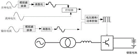
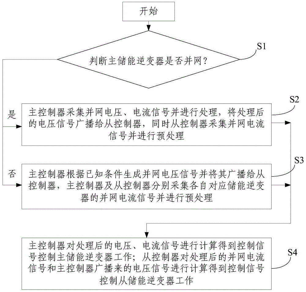
[0042] Step 1. Build a single three-phase energy storage inverter model with a capacity of 100kW and a rated output voltage of 380V. The controller has two modes of voltage frequency control and power control. In the case of off-grid, the voltage frequency control mode is adopted. Then judge whether the energy storage inverter is connected to the grid or off-grid. If the energy storage inverter is connected to the grid, go to step 2, otherwise go to step 3;

[0043] Step 2. Under the grid-connected condition of the energy storage inverter, sample the grid-connected voltage signal and current signal, send the sampled signal to the analog filter for filtering, and then send it to the discretization module for discretization to obtain a digital voltage Signals and digital current signals are sent to the controller. Under grid-connected conditions, the real-time phase information of ...

Embodiment 2

[0046] Example 2: Simulation experiment of three three-phase energy storage inverters running in parallel off-grid

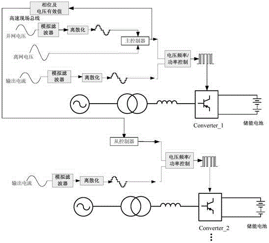
[0047] Step 1. Build a three-phase energy storage inverter model, with a single capacity of 100kW and a rated output voltage of 380V. The controller has two modes of voltage frequency control and power control, and the voltage frequency control mode is adopted in the case of off-grid. The system adopts and figure 2 The same main wiring as shown, the energy storage battery is placed inside the block diagram of the energy storage controller Converter.

[0048] Step 2. Start the first energy storage inverter, Converter_1, and put in a 100kW load at the same time. After one cycle of the simulation environment, the first calculation is completed, and the bus voltage is established. After 5 cycles, the system controls the bus voltage to be normal.

[0049] Step 3. When t=0.05 seconds, under fast phase control, the second energy storage inverter Converter_2 is put in...


PUM


Abstract

The invention discloses a networking control method of energy storage inverters based on quasi real-time synchronous signals, and relates to the field of micro-grid operational control. The networking control method includes the steps that the S1, whether a main energy storage inverter is in grid connection is judged, if yes, the S2 is carried out, and if not, the S3 is carried out; the S2, a master controller collects grid connection voltage and current signals, processes the voltage and current signals, broadcasts the processed voltage signals to a slave controller and meanwhile the slave controller collects grid connection current signals from the slave controller and carries out preprocessing; the S3, the master controller generates grid connection voltage signals according to known conditions and broadcasts the grid connection voltage signals to the slave controller, and the master controller and the slave controller collect the grid connection current signals of the corresponding energy storage inverter and carry out preprocessing respectively; the S4, the master controller carries out computation on the processed voltage and current signals to obtain control signals so as to control the main energy storage inverter to work; the slave controller carries out computation on the processed grid connection current signals and voltage signals broadcast from the master controller to obtain control signals to control a slave energy storage inverters to work.

Description

technical field [0001] The invention relates to a networked control method of an energy storage inverter based on a quasi-real-time synchronous signal, and relates to the field of micro-grid operation control. Background technique [0002] Energy storage is a necessary technical means for microgrids to absorb renewable energy power generation on site. The rapid development of intermittent energy power generation industries represented by wind power and photovoltaics will promote the development of large-capacity energy storage industries. Under the coordinated control of the micro-grid, energy storage technology solves the randomness and volatility of new energy power generation to a large extent, can realize the smooth output of renewable energy power generation, and can effectively adjust the grid voltage caused by new energy power generation. The change of frequency and phase makes the intermittent power supply easily and reliably merged into the large power grid. In add...

Claims


Application Information

Patent Timeline
Patent Type & Authority Patents(China)
IPC IPC(8): H02J3/40H02M7/48
Inventor 井天军杨仁刚盛万兴苏剑唐云峰王文成王江波孙钦斐
Owner STATE GRID CORP OF CHINA
Why Eureka
Try Eureka