
Improved tail gas condensation separator in polysilicon production

A technology of condensation separation and polysilicon, which is applied in the field of reduction tail gas recovery, can solve the problem of high energy consumption, and achieve the effect of saving equipment investment and operating costs, and saving equipment investment costs.

Active Publication Date: 2014-03-05
XINTE ENERGY
View PDF5 Cites 3 Cited by
  • Summary
  • Abstract
  • Description
  • Claims
  • Application Information

AI Technical Summary

Problems solved by technology

[0004] The object of the present invention is to solve the above-mentioned high energy consumption problem, and provide a tail gas condensation and separation device in polysilicon production, which uses the cooling capacity and heat in the condensation process to exchange heat with each other, and makes full use of the cooling capacity, so as to achieve better condensation and separation The effect and the purpose of reducing production energy consumption

Method used


Image

  • Improved tail gas condensation separator in polysilicon production
  • Improved tail gas condensation separator in polysilicon production

Examples


Embodiment Construction

[0034] In order to enable those skilled in the art to better understand the technical solutions of the present invention, the present invention will be further described below in conjunction with the accompanying drawings.

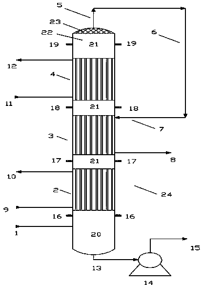
[0035] In this embodiment, the structure of a device used for the improved polysilicon production tail gas condensation and separation method is as follows figure 2As shown, the reduction tail gas at 120°C is left in the reduction tail gas liquid collector (20) through the reduction tail gas inlet (1), and is initially separated under the action of gravity, and the separated chlorosilane liquid enters the reduction tail gas liquid collector (20); the gas enters the circulating water heat exchanger (2) for heat exchange, the outlet temperature of the circulating water heat exchanger (2) is 30°C to 50°C, and the condensed vapor-liquid mixture enters the reduction tail gas and then In the distributor (21), further vapor-liquid separation is carried out under...


PUM


Abstract

The invention relates to the field of reduction tail gas recovery in polysilicon production, the current separators are composed of a plurality of heat exchangers with different temperature in a distributed and horizontal distribution, thereby the energy consumption is high, and the cold amount can not be fully recovered and used. The invention provides a stereo combination type separating apparatus, a reduction tail gas liquid collector, a circulating water heat exchanger, a gas-gas heat exchanger and a Freon heat exchanger are connected in order from down to top, a reduction tail gas redistributor and a demister are arranged between the heat exchangers and at the top of the heat exchanger, the whole apparatus is in a tower structure, a reduction tail gas inlet is provided at the side surface of the reduction tail gas liquid collector, and a chlorosilane liquid outlet is separated and equipped with the bottom of the reduction tail gas liquid collector. The improved tail gas condensation separator has the advantages that the energy consumption is saved, the basic construction cost is saved, the equipment maintenance is convenient, separating effect is high, and the equipment operation cost is low.

Description

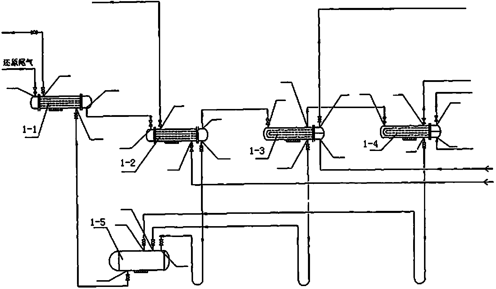
technical field [0001] The invention belongs to the field of recovery of reduction tail gas in polysilicon production, and in particular relates to a method for condensation and separation of reduction tail gas. Background technique [0002] In the polysilicon production process, the reduction tail gas condensation separation system is to separate the condensable chlorosilane from the non-condensable hydrogen and most of the hydrogen chloride in the reduction tail gas. [0003] The traditional exhaust gas recovery method is as attached figure 1 Shown is that the reduction tail gas is gradually cooled down through the distributed horizontally distributed circulating water heat exchanger, air-gas heat exchanger, frozen brine heat exchanger and Freon heat exchanger to achieve the purpose of separation. This method requires a large amount of cooling capacity to separate the condensable components from the non-condensable components in the tail gas, which requires not only a Fre...

Claims


Application Information

Patent Timeline
IPC IPC(8): B01D53/00B01D53/18B01D5/00B01D45/02B01D50/00C01B33/107
CPCY02P70/10
Inventor 王东陈文岳罗永军
Owner XINTE ENERGY
Learn More