Implanting machine for nuclear power plant reactor king bolt and method for implanting bolt

A technology for nuclear power plant reactors and main bolts, applied in metal processing, metal processing equipment, manufacturing tools, etc., can solve the problems of large impact force, large error, unstable load, etc., to eliminate alignment errors, reduce pressure and impact , the effect of smooth start import ability

Active Publication Date: 2014-03-05
CHENGDU HAIGUANG NUCLEAR POWER TECH SERVICE CO LTD
View PDF8 Cites 17 Cited by
  • Summary
  • Abstract
  • Description
  • Claims
  • Application Information

AI Technical Summary

Problems solved by technology

[0013] The purpose of the present invention is to overcome the problems of large impact force, large error and unstable load when the existing single bolts are implanted, and a machine for implanting main bolts in nuclear power plant reactors and a method for implanting main bolts are designed. The implanting machine and method solve the problems of large impact force, large error and unstable load when the existing single bolt is implanted

Method used


Image

  • Implanting machine for nuclear power plant reactor king bolt and method for implanting bolt
  • Implanting machine for nuclear power plant reactor king bolt and method for implanting bolt
  • Implanting machine for nuclear power plant reactor king bolt and method for implanting bolt

Examples


Embodiment 1

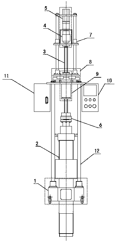
[0041] like figure 1 As shown, the implanter for the main bolt of the nuclear power plant reactor includes a base 1 and a drive assembly, a bracket 12 is arranged between the base 1 and the drive assembly, the bottom end of the bracket 12 is fixed on the base 1, and the top end of the bracket 12 is fixed There is an adaptive centering component 8, and a guide component 7 is arranged above the self-adaptive centering component 8, and the two ends of the guide component 7 are respectively connected with the self-adaptive centering component 8 and the drive component, and the bottom end of the self-adaptive centering component 8 A control box 11 is fixed, and the control box 11 is fixed on the bracket 12. The bottom end of the drive assembly is connected with a ball screw 3, and the ball screw 3 is fitted with a load balancer assembly 9. The load balancer assembly 9 is fixed and passes through the After adapting to the centering component 8, it is arranged inside the bracket 12. ...

Embodiment 2

[0043] like Image 6 As shown, on the basis of Embodiment 1, the load balancer assembly 9 includes a spring sleeve 21 and a lead screw nut 16 and a spring preloaded nut seat 24 arranged at both ends of the spring sleeve 21, and the lead screw nut 16 is arranged on the spring preloaded nut seat 24. Just above the tightening nut seat 24, and one end of the lead screw nut 16 and the spring preload nut seat 24 are all arranged inside the spring sleeve 21; 16 and the spring preloaded nut seat 24, a spring 20 is arranged between the spring sleeve 19 and the leading screw 3, the spring sleeve 19 is slidably matched with the inner wall of the spring sleeve 21, and the bottom end of the spring 20 is connected to the spring preloaded nut seat 24. The top is in contact, and a sensor 18 is arranged between the spring sleeve 19 and the screw nut 16. , spring sleeve 19, spring 20 and spring preload nut seat 24. The spring sleeve 21 is the basic part of the bearing spring 20. The spring 20...

Embodiment 3

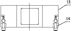
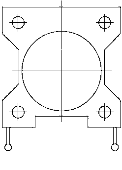
[0045] figure 2 is the front structure diagram of base 1, image 3 is its top view, Figure 4 It is a bottom view. On the basis of the above-mentioned embodiment, the circular through hole with a diameter of φ can make the base 1 pass through the main bolt and sit on the top cover. The base 1 comprises a body 13 and a retractable quick positioning stop pin 14 arranged on the side wall of the body 13, and the positioning stop pin 14 fixes the body 13 and the reactor top cover, from Figure 4 It can be seen that there are five electromagnetic coils 15 inlaid on the bottom of the base 1, four of which are respectively distributed on the four corners of the bottom surface of the body 13, and another electromagnetic coil 15 is arranged on the center line of the bottom surface of the body 13. A circular through hole with a diameter of φ is arranged at the top center of the body 13 , the through hole runs through the body 13 , and the bottom end of the bracket 12 is fixed to the t...


PUM


Abstract

The invention discloses an implanting machine for a nuclear power plant reactor king bolt and a method for implanting the bolt. A support is arranged between a machine base and a drive assembly, a self-adaptive centering assembly is fixed to the support, the drive assembly is connected with a lead screw, the lead screw is sleeved with a load balancer assembly, a clutch is connected with a chuck, the implanting machine is connected with the king bolt in a sleeved mode, an electromagnetic coil is energized, and the chuck is connected with the head of the king bolt after the clutch is disengaged; the king bolt stops when being close to a reactor container king bolt hole; the king bolt is guided into the king bolt hole, and a balance load is adjusted to be at an ideal value; when the king bolt moves downwards to a preset position, the load of a load balancer is reduced to be at an initial value, and the chuck of the implanting machine is lifted to an original position. The implanting machine is quick to locate, the king bolt guide-in process is stable, impact force is small, centering errors of the king bolt and the king bolt hole are automatically eliminated, pressure and impact on a thread auxiliary surface can be reduced to the maximum, stable load balance capacity is kept, and the change situation of the gravity of the king bolt can be tracked in real time in the whole course.

Description

technical field [0001] The invention relates to a machine for implanting a main bolt of a nuclear power plant reactor and a method for implanting the main bolt, belonging to the field of mechanical manufacturing. Background technique [0002] The installation of the main bolts of the nuclear power plant reactor is an essential key process before the new nuclear power plant is loaded and in the process of refueling and overhaul of all nuclear power plants. The installation of the main bolt is divided into two steps: 1) screw the main bolt into the main screw hole of the reactor vessel, and 2) pre-tighten the main bolt with a bolt tensioning machine. [0003] At present, various nuclear power plants have different methods for screwing the main bolt into the main screw hole of the reactor vessel, which can be roughly divided into three categories. The first type is to use the main bolt screw-in function in the integral bolt tensioning machine to screw in the main bolt; the sec...

Claims


Application Information

Patent Timeline
Patent Type & Authority Applications(China)
IPC IPC(8): B23P19/06
CPCB23P19/06
Inventor 胡运峰杨炯平黄勇徐波郭科科李春陈先庆秦小军刘庭明
Owner CHENGDU HAIGUANG NUCLEAR POWER TECH SERVICE CO LTD
Why Eureka
Try Eureka