
Small six-axis simultaneous sharpening unit for milling cutters

A six-axis linkage, small-scale technology, applied in the direction of grinding drive devices, milling cutters, milling machine equipment, etc., can solve the problems of large volume, low work efficiency, poor stability of machine tools, etc., and achieve small volume, simple structure and wide application range Effect

Inactive Publication Date: 2016-06-01
广州市技师学院
View PDF5 Cites 0 Cited by
  • Summary
  • Abstract
  • Description
  • Claims
  • Application Information

AI Technical Summary

Problems solved by technology

At present, there are five-axis linkage equipment and four-axis linkage equipment for grinding end mills. For end mills with complex curved surfaces, the existing tool processing devices cannot meet their sharpening requirements.
Because the existing tool processing device has the following disadvantages: (1) It cannot be fed along the axial direction of the end mill, and its operation is difficult
(2) In the process of processing, there are situations such as excessive cutting resistance, insufficient chip removal, uneven grinding, etc.
(3) The control error of each included angle of the end mill is large, resulting in low machining accuracy, poor quality, and low work efficiency
(4) At present, the grinding wheel of the grinding processing equipment is set on the rotating shaft, and the movement track of the grinding wheel is adjusted through the rotation of the grinding wheel. Due to the large size and weight of the grinding wheel, the rotation of the grinding wheel raises the center of gravity of the machine tool, resulting in poor stability of the machine tool

Method used


Image

  • Small six-axis simultaneous sharpening unit for milling cutters
  • Small six-axis simultaneous sharpening unit for milling cutters
  • Small six-axis simultaneous sharpening unit for milling cutters

Examples


specific Embodiment 1

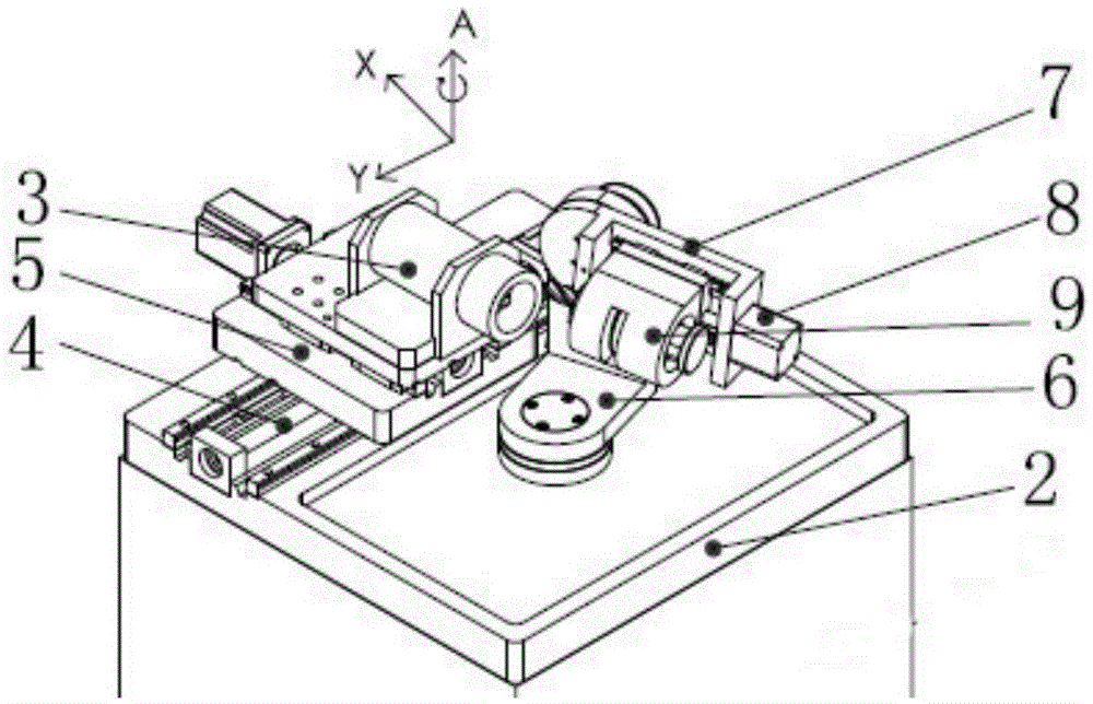
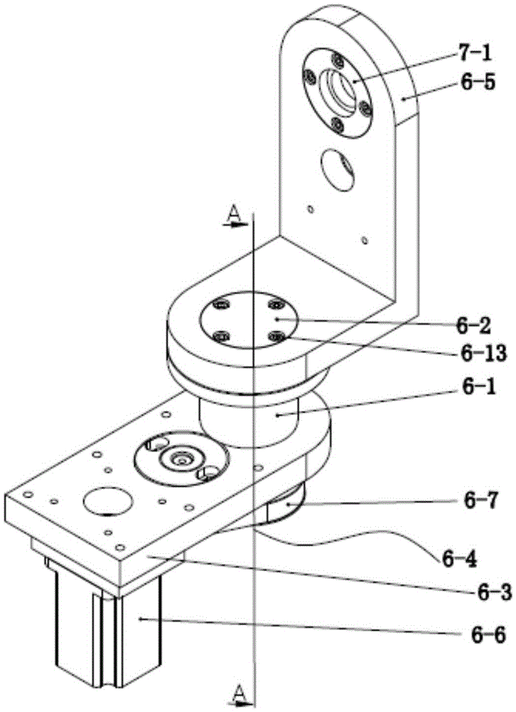
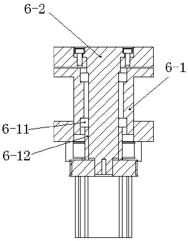
[0034] Such as figure 1 As shown, this embodiment includes a small bed 2, on which a milling tool holder, a grinding wheel mechanism 3 and a six-axis linkage sharpening mechanism are arranged. The six-axis linkage sharpening mechanism includes a Y-axis linear movement mechanism 4, an X-axis Linear moving mechanism 5, Z-axis linear moving mechanism 8, A-axis rotating mechanism 6, B-axis rotating mechanism 7 and C-axis rotating mechanism 9, A-axis rotating mechanism 6 is installed on the surface of small bed 2 through A-axis, A-axis rotating mechanism The vertical turret of 6 is connected with the B axis of the B axis rotation mechanism 7, the Z axis linear movement mechanism 8 is arranged in the horizontal turret of the B axis rotation mechanism 7, and the C axis rotation mechanism 9 is connected with the Z axis linear movement mechanism 8, Forming a four-axis linkage connection structure, the end mill tool holder 10 is set on the C-axis rotating mechanism 9; the Y-axis linear ...


PUM


Abstract

The invention relates to a small-sized six-shaft linkage sharpening unit for milling tools. The small-sized six-shaft linkage sharpening unit for milling tools is characterized by comprising a small bed, a milling tool carrier, a grinding wheel mechanism and a six-axis linkage sharpening mechanism. The six-shaft linkage sharpening mechanism comprises a Y-axial linear movement mechanism, an X-axial linear movement mechanism, a Z-axial linear movement mechanism, an A-axial rotating mechanism, a B-axial rotating mechanism and a C-axial rotating mechanism. The A-axial rotating mechanism drives the milling tool carrier to rotate around an axis A so as to control main deflecting angle of the milling tool carrier; the B-axial rotating mechanism drives the milling tool carrier to rotate around an axis perpendicular to the axis A; the Z-axial linear movement mechanism drives the milling tool carrier to linearly move on the Z-axial linear movement mechanism; the C-axial rotating mechanism drives the milling tool carrier to rotate so as to control each blade of the milling tool carrier; the Y-axial linear movement mechanism and the X-axial linear movement mechanism drive the grinding wheel mechanism to linearly move along axes Y and X; thus the six-axis linkage sharpening unit for milling tools is formed. The small-sized six-shaft linkage sharpening unit for milling tools has the advantages of simple structure, small size, light weight, capability of providing diverse grinding tools and wide range of application.

Description

technical field [0001] The invention relates to a processing device for milling cutters, in particular to a small six-axis linkage sharpening device for milling cutters, and is especially suitable for grinding, teaching and small-scale mechanical processing of end mills. It belongs to the technical field of teaching equipment and numerical control machine tools. Background technique [0002] In production practice, a large number of end mills need to be used. There are many types of end mills, and they are the most complex surface in CNC machine tool machining. End mills End mills are divided into: flat end mills, ball end mills, flat end mills with chamfering, forming milling cutters, chamfering knives, T-shaped knives, toothed knives and rough leather knives. The main cutting edge of the end mill is the circumferential toothed edge on the outer circle of the blade, and the cutting edge on the end face is the auxiliary cutting edge. At present, there are five-axis linkag...

Claims


Application Information

Patent Timeline
Patent Type & Authority Patents(China)
IPC IPC(8): B24B3/02
CPCB24B3/02B24B47/20
Inventor 余焕强陈林生廖红胜
Owner 广州市技师学院
Learn More