
Patsnap Eureka
For R&D, Patsnap Eureka makes reading and utilizing patents & technical documents easy.
Patsnap Eureka AIR
Designed for self-driven R&D workflows. Generate viable solutions, solve complex R&D challenges, empower your innovation with AI.

Patsnap Eureka Materials
Designed for material experts only. Revolutionize your material R&D, from search, analyze, to developing new materials.

TechResearch
Generate reliable direction feasibility study reports for your R&D in just a few steps.

TechSeek
Discover and master advanced knowledge NOW. Basics, ideas, possibilities, all at once.

TechMind
As an expert in R&D Theories, TechMind can generates customized viable solutions instantly.

TechRisk
Analyze your overall solution with one click, know your potential R&D risks in advance.

TechMonitor
Get weekly tech updates, stay abreast of the latest tech innovations and key insights.
LED bulb lamp
A technology of LED bulbs and LED light boards, which is applied in lighting devices, cooling/heating devices of lighting devices, light sources, etc., can solve problems such as electricity safety, achieve high safety performance, effective heat, and reduce daily electricity consumption. The effect of security risks
- Summary
- Abstract
- Description
- Claims
- Application Information
AI Technical Summary
Problems solved by technology
Method used
Image

Examples
Embodiment 1
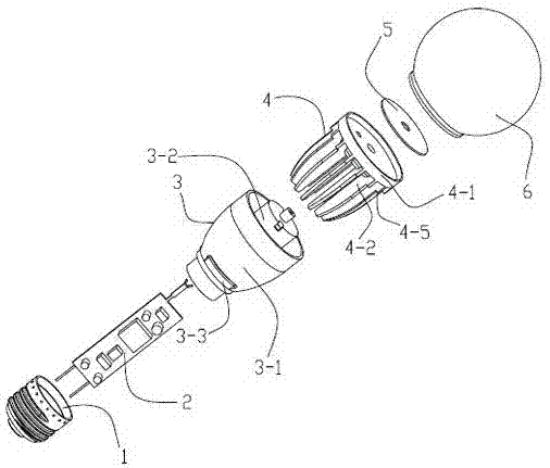
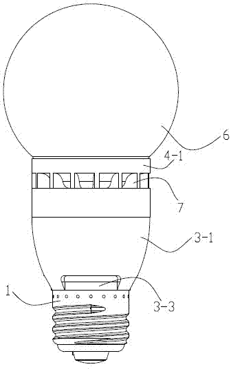
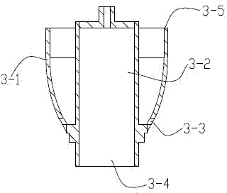
[0022] like Figure 1-5 As shown, the LED bulb lamp provided in this embodiment includes a lampshade 6, an LED lamp panel assembly 5, an insulating base 3, a radiator 4, a power supply assembly 2 and a lamp holder 1, and the insulating base 3 includes a The cylindrical housing chamber 3-2 and the bottom of the component 2 are connected to the outer surface of the cylindrical housing chamber 3-2, and are located on the outer wall 3-1 of the cylindrical housing chamber 3-2. There is an air inlet 3-3 at the junction of the cylindrical housing chamber 3-2, the power supply assembly 2 is located in the cylindrical housing chamber 3-2, and the lamp holder 1 is socketed at the port 3-4 of the cylindrical housing chamber 3-2. Above, the radiator 4 includes a middle plate 4-1 and a heat dissipation rib 4-2 with a gap ring arranged on one side of the middle plate 4-1, and the outer edge 4-4 of the heat dissipation rib 4-2 forms a step On the surface 4-5, the heat dissipation rib 4-2 is...
Embodiment 2
[0025] The general structure of the LED bulb lamp provided in this embodiment is consistent with that of Embodiment 1, but in order to improve the illumination angle of the LED bulb lamp, it can realize wide-angle lighting similar to that of an incandescent lamp, such as Figure 7 and Figure 8 As shown, the LED light board assembly 5 includes a multi-lobed aluminum substrate 5-1 and a double-sided LED light bar 5-2 connected to each petal of the aluminum substrate 5-1. The above-mentioned aluminum substrate 5- 1 is fixed on one side of the intermediate disc 4-1.
Embodiment 3
[0027] The general structure of the LED bulb lamp provided in this embodiment is consistent with that of Embodiment 2, but in order to reduce the influence of the radiator 4 on the illumination of the LED lamp panel assembly 5, and further improve the illumination effect of the LED bulb lamp, as shown in Figure 9 and Figure 10 As shown, an LED lamp panel installation platform 4-3 is provided on one side of the intermediate plate 4-1, and the aluminum substrate 5-1 of the LED lamp panel assembly 5 is fixed on the above-mentioned LED lamp panel installation platform 4-3. 3 on.
PUM
 Abstract
Description
Claims
Application Information
 - R&D Engineer
- R&D Manager
- IP Professional
- Industry Leading Data Capabilities
- Powerful AI technology
- Patent DNA Extraction
Browse by: Latest US Patents, China's latest patents, Technical Efficacy Thesaurus, Application Domain, Technology Topic, Popular Technical Reports.
© 2024 PatSnap. All rights reserved.Legal|Privacy policy|Modern Slavery Act Transparency Statement|Sitemap|About US| Contact US: help@patsnap.com