
Ring conveying system of calcium carbide furnace

A conveying system, calcium carbide furnace technology, applied in furnaces, furnace components, electric charge control, etc., can solve problems such as difficult repair and maintenance, low operating efficiency, increased safety hazards, etc., to save cooling workshops, facilitate maintenance, and improve production efficiency Effect

Active Publication Date: 2015-06-03
DALIAN HUARUI HEAVY IND GRP CO LTD
View PDF7 Cites 0 Cited by
  • Summary
  • Abstract
  • Description
  • Claims
  • Application Information

AI Technical Summary

Problems solved by technology

It requires a lot of labor from the calcium carbide furnace to the cooling and lifting, the operation efficiency is low, and many safety hazards are added. The labor cost is also very high. At the same time, it needs to occupy a cooling workshop of about 1500m2, and the sensible heat cannot be recycled.
[0004] In 2012, our company designed a set of "calcium carbide furnace conveying system" for Zhongtai. Its patent application number is 201210133221.7. By setting the automatic opening and closing pot door, it eliminates the process of manual removal of pot ears and reduces the labor intensity of workers. The transportation of calcium carbide is realized through the hydraulic drive system, which improves safety. However, the length of the track is several hundred meters and takes up a large cooling workshop. Manual assistance is still required to complete the clamping of calcium carbide, and the number of calcium carbide pots is as large as 118. , complex structure, difficult to overhaul and maintain, low reliability, and high manufacturing cost

Method used


Image

  • Ring conveying system of calcium carbide furnace
  • Ring conveying system of calcium carbide furnace
  • Ring conveying system of calcium carbide furnace

Examples


Embodiment Construction

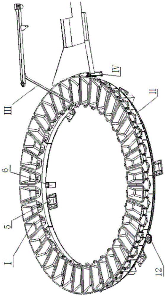
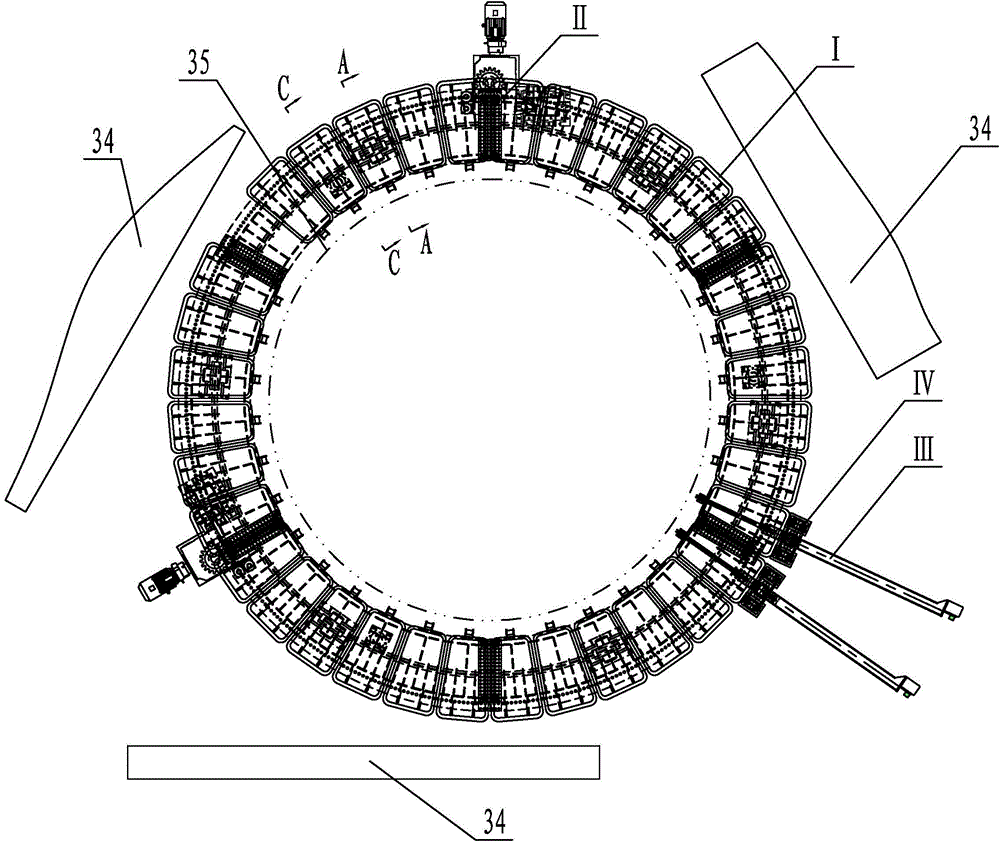
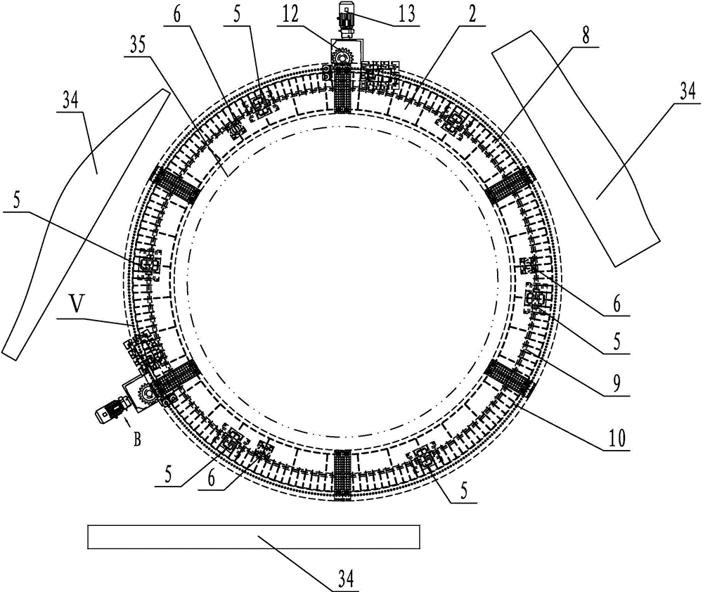
[0028] The content of the present invention will be described in detail below in conjunction with the accompanying drawings: The calcium carbide furnace circular conveying system of the present invention is composed of calcium carbide pot I, disc drive system II, tipping mechanism III, and vibration unloading device IV. There are 36 calcium carbide pots I around the furnace body 35 of the calcium carbide furnace, and the calcium carbide pots I are connected to the disk 2 through the pin shaft i-1. The disc 2 is arranged concentrically with the calcium carbide furnace and surrounds the outside of the furnace body. Tilting mechanism III is arranged between two burn-through platforms 34, on the outside of disk drive system II. There are two sets of tilting mechanism III, arranged radially, with the center line pointing to the center of the circle. The vibrating unloading device IV is arranged outside the disc drive system II, just below the tilting mechanism III, and when the cal...


PUM


Abstract

The invention discloses a ring conveying system of a calcium carbide furnace. The ring conveying system is characterized by comprising calcium carbide pots installed on a disc driving mechanism, a tilting mechanism arranged on the outer side of the disc driving mechanism, and a vibration discharging device arranged beside the tilting mechanism. Demoulding of calcium carbide is changed into gravity demoulding from clamping demoulding, manual assistance is not needed, the labor intensity of workers is relieved, and the calcium carbide is mechanically discharged form the furnace. A rail is arranged to be a round rail, the number of the calcium carbide pots is reduced to 36 from 118, and the demoulding position of the calcium carbide is lifted to the front of the furnace from a cooling workshop, the cooling workshop is removed, the operation efficiency of a pot vehicle is improved, equipment losses are reduced, and safety production is achieved. Driving with a hydraulic cylinder is replaced by electric driving, a hydraulic station does not need to be independently configured any more, the manufacturing cost is reduced, and maintenance is facilitated. The system is higher in reliability, each component for use has a spare component, so that when the component is damaged, the system cannot break down, and losses of production are avoided. An original calcium carbide pot is of a long cone split structure, and the existing calcium carbide pot is a pyramid and can be integrally cast and easier to machine.

Description

technical field [0001] The invention relates to a calcium carbide furnace. In particular, it relates to a calcium carbide conveying system after the calcium carbide is discharged from the furnace. Background technique [0002] Calcium carbide, whose chemical name is calcium carbide, is produced by reacting calcium oxide and coke in a calcium carbide furnace at a high temperature of 1800-2200°C by means of arc heat and resistance heat. The calcium carbide furnace is released about once an hour, and the molten calcium carbide is discharged into the calcium carbide pot. The calcium carbide pot sits on the furnace trolley and is pulled down to the cooling workshop by the winch. [0003] At present, the transportation of calcium carbide in China is mostly based on manual observation and manual control of the hoist to pull the calcium carbide pot to the cooling workshop. After the calcium carbide is cooled, the calcium carbide is manually lifted from the calcium carbide pot. A l...

Claims


Application Information

Patent Timeline
Patent Type & Authority Patents(China)
IPC IPC(8): F27D3/00
Inventor 赵兴张彦萍张森王圣茂高旭李荣军
Owner DALIAN HUARUI HEAVY IND GRP CO LTD
Learn More