
Full-solid-state high-voltage pulse current source with unipolar pulse output

A pulse output, high-voltage pulse technology, applied in the field of power supply, can solve the problems of short life, limited life, low withstand voltage of the power supply system, etc., and achieve the effects of low cost, not easy to overvoltage, and system safety.

Active Publication Date: 2014-03-05
FUDAN UNIV
View PDF5 Cites 10 Cited by
  • Summary
  • Abstract
  • Description
  • Claims
  • Application Information

AI Technical Summary

Problems solved by technology

[0003] Conventional power electronics technology mainly adopts the method of inductance combined with a circuit breaker to obtain pulse current. On the one hand, because the existing circuit breaker is usually a low-voltage device, pulse overvoltage is often generated when the current is disconnected. When the amplitude of the overvoltage exceeds the switch When the withstand voltage of the device is lower than the withstand voltage value of the device, the switch device is prone to breakdown and damage, so the conventional pulse current source circuit breaker needs to be added with an overvoltage protection or a peak voltage absorbing circuit; on the other hand, due to the low withstand voltage of the power system, it is difficult to It is used in occasions that require both high voltage and pulse current, and the high voltage circuit breaker is not yet mature, and the stability is not enough, and the service life is limited
The impulse voltage generator used in high-voltage occasions adopts a Marx structure. The entire device is composed of a capacitor, an isolation resistor (or inductance) and a spark gap. The generated pulse voltage waveform is difficult to control, the amplitude is difficult to adjust, and the output current is uncontrollable. It is difficult to meet the requirements in test occasions. For example, in the test of high-voltage varistors, both high voltage and relatively constant output current are often required.
A typical high-voltage pulse current source often needs a circuit breaker to realize, but the current high-voltage circuit breaker has the disadvantages of unstable operation and short life, and it is difficult to obtain better output results, which affects the test results.

Method used


Image

  • Full-solid-state high-voltage pulse current source with unipolar pulse output

Examples


Embodiment Construction

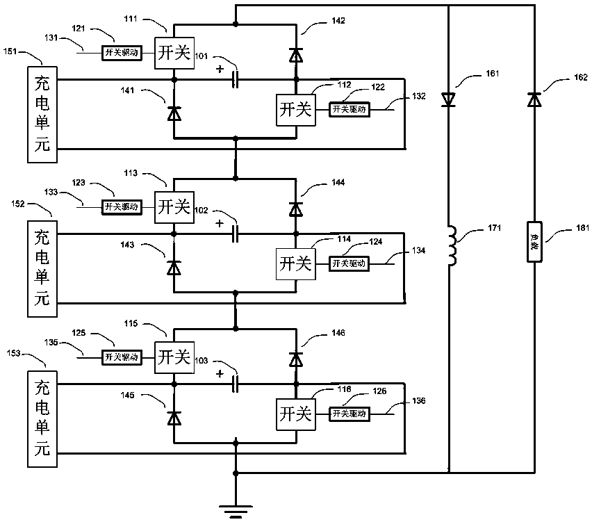
[0024] The invention relates to a method for realizing a pulse current source. With the synchronous turn-on of the semiconductor switch, the low-voltage capacitors are connected in series to discharge the inductor, thereby generating a current pulse. When the switching device is turned off, the inductor continues to flow through the load, and a high-voltage pulse is generated on the load. Since the inductor current cannot change suddenly, the load on the load The high voltage pulse amplitude is determined by the load characteristics.

[0025] The specific example of the implementation of the present invention uses three-stage discharge cells in series as the basic structure, and the number of series-connected stages of discharge cells in practical applications can also be flexibly increased or decreased according to needs. Its description is as follows:

[0026] figure 1 In the illustrated embodiment, in the figure, there are three basic discharge units, which are connected ...


PUM


Abstract

The invention belongs to the field of power supply technologies, and particularly relates to a full-solid-state high-voltage pulse current source with unipolar pulse output. The full-solid-state high-voltage pulse current source with unipolar pulse output is composed of basic discharge units which are connected in series, a current in a load can be maintained to be constant by using inductors and high voltage diodes, and a voltage of the load is determined by load characteristics and parameters of an inductance current simultaneously. The current source will not be influenced by conditions of short circuit of the load when the current source is used for a pulse voltage-resistance test, and the current source can effectively supply a stable pulse current when the current source is used for testing the voltage resistance of a voltage-sensitive device.

Description

technical field [0001] The invention belongs to the technical field of power supplies, and in particular relates to an all-solid-state high-voltage pulse current source with unipolar pulse output. Background technique [0002] With the development of pulse power technology, the application of high-voltage pulse current source is becoming more and more extensive. In addition to conventional laser pumping, ion implantation material modification, EDM, switch electrode aging and gas discharge related applications, some high-voltage The research on pulse characteristics of devices has also attracted extensive attention, such as materials and pulse withstand voltage characteristics of devices. At present, most devices for testing withstand voltage are mainly DC high-voltage power supplies. When it comes to impulse withstand voltage, impulse voltage generators are often used as high-voltage generating devices. [0003] Conventional power electronics technology mainly adopts the me...

Claims


Application Information

Patent Timeline
IPC IPC(8): H02M9/02
Inventor 邱剑刘克富卢元达王永刚
Owner FUDAN UNIV
Learn More