Multi-rotor unmanned aerial vehicle

A multi-rotor unmanned aerial vehicle technology, applied in the field of multi-rotor unmanned aerial vehicles, can solve the problems of limiting the load and hovering performance of the aircraft, the functional division of the rotor is not clear enough, the mechanical structure is complicated, etc. Strengthen the rotor attitude control function and the effect of simple mechanical structure

Inactive Publication Date: 2014-03-12
NANJING CARVEDGE TECH
View PDF10 Cites 58 Cited by
  • Summary
  • Abstract
  • Description
  • Claims
  • Application Information

AI Technical Summary

Problems solved by technology

While the layout is beautiful and controllable, due to the mechanical structure and control requirements, the relatively small rotor size also limits the load and hover performance of the aircraft, which makes the practicability slightly compromised;
[0010] 2) The aerodynamic layout of rotor function partitions,

Method used


Image

  • Multi-rotor unmanned aerial vehicle
  • Multi-rotor unmanned aerial vehicle
  • Multi-rotor unmanned aerial vehicle

Examples


Embodiment Construction

[0029] The accompanying drawings disclose non-restrictive structural schematic diagrams of the embodiments involved in the present invention; the technical solutions of the present invention will be described in detail below in conjunction with the accompanying drawings.

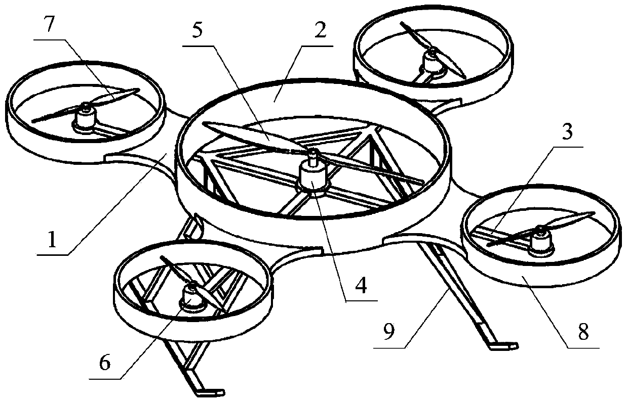
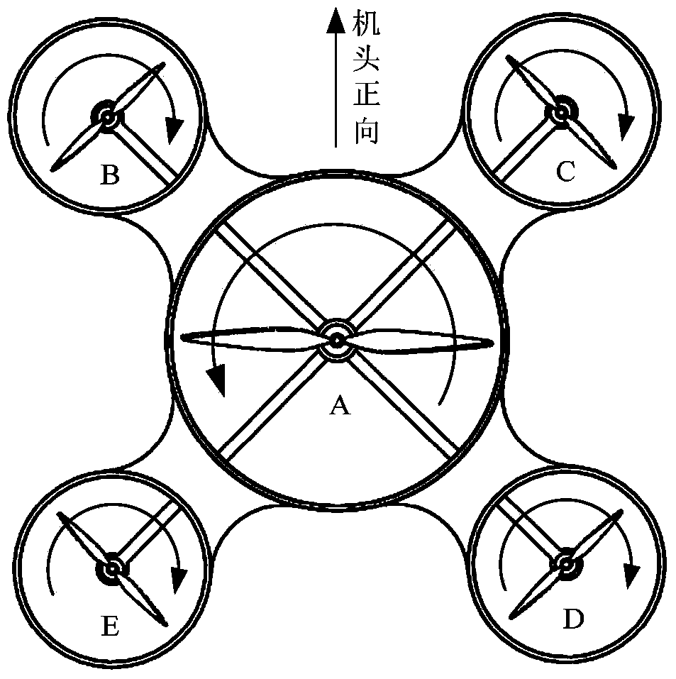
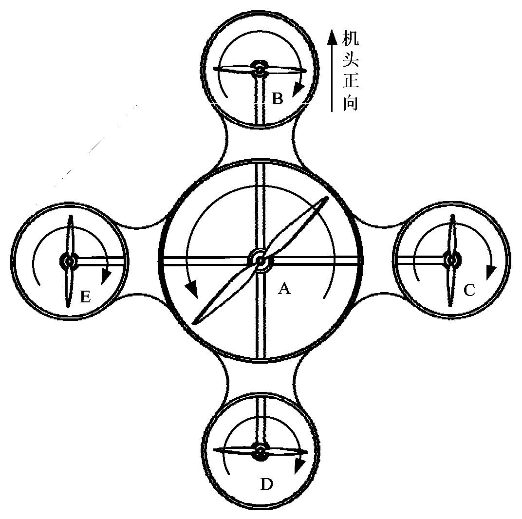
[0030] Such as Figure 1-3 As shown, Embodiment 1 of the present invention discloses a five-rotor aeroplane, comprising a fuselage 1 , a central rotor assembly, a peripheral rotor assembly, and a landing gear 8 . The center of the fuselage 1 is provided with a central duct 2, and the periphery is radially and circumferentially evenly distributed with rotor support arms 3; the central rotor assembly is located inside the central duct 2 of the fuselage and is coaxial, including a central rotor motor 4 and a central rotor 5; The center rotor motor 4 is fixed on the fuselage center, and the center rotor 5 is installed on the rotating shaft of the center rotor motor 4 and is driven by the center rotor motor 4 to ...


PUM


Abstract

The invention discloses a multi-rotor unmanned aerial vehicle which comprises a body, wherein a central duct is arranged at the center of the body; n rotor support arms are circumferentially and uniformly distributed in a radial manner on the periphery of the central duct, and n is greater than or equal to 3; a central rotor assembly is coaxially mounted in the central duct; the central rotor assembly comprises a central rotor motor and a central rotor connected with an output shaft of the central rotor motor; the central rotor motor is fixedly mounted at the center of the body; a peripheral rotor assembly is mounted on each rotor support arm; the peripheral rotor assembly comprises a peripheral rotor motor and a peripheral rotor connected with an output shaft of the peripheral rotor motor; the peripheral rotor motor is mounted on the rotor support arm; the size of the central rotor is greater than that of the peripheral rotor; the rotation direction of the central rotor is opposite to that of the peripheral rotor. Therefore, the multi-rotor unmanned aerial vehicle disclosed by the invention has the advantages of novel pneumatic layout, stable and reliable hovering and strong load capacity and is easy to realize in engineering.

Description

technical field [0001] The invention relates to a multi-rotor unmanned aerial vehicle with a symmetrical layout, which belongs to the technical field of design and control of unmanned aerial vehicles. It can carry various mission equipment and is widely used in aerial photography, power inspection, environmental monitoring, forest fire prevention, and disaster situations. Patrol, anti-terrorist lifesaving, military reconnaissance, battlefield assessment and other fields. Background technique [0002] Multi-rotor unmanned aerial vehicle is a new type of unmanned aerial vehicle with vertical take-off and landing and stable hovering capabilities. Compared with traditional rotor helicopters, it has simplified mechanical structure, simple power control, safe rotor size, maneuverability and autonomous control. It has become one of the hotspots in the research field of new micro-miniature drones. The aircraft generally adopts a plurality of forward and reverse reversing rotors sym...

Claims


Application Information

Patent Timeline
IPC IPC(8): B64C27/08B64C27/12
Inventor 李少斌王世勇杨忠陈阳梁焜许家浩钟山
Owner NANJING CARVEDGE TECH
Why Eureka
Try Eureka