
Gas end cylindrical surface combined sealing device provided with spiral groove

A sealing device and end face sealing technology, applied in the direction of engine sealing, engine components, mechanical equipment, etc., can solve the problems of deformation of sealing position, decrease of system working stability, excessive leakage, etc., so as to reduce contact wear and realize deformation The effect of adaptability

Inactive Publication Date: 2014-03-12
BEIHANG UNIV
View PDF5 Cites 0 Cited by
  • Summary
  • Abstract
  • Description
  • Claims
  • Application Information

AI Technical Summary

Problems solved by technology

[0004] In order to overcome the deformation of the sealing position due to the change of the working state of the system during the working process of the high-speed rotor system, which will cause the contact wear of the sealing ring, the decrease of the working stability of the system or the excessive leakage, and at the same time adapt to the space of the non-shaft end sealing position along the high-speed rotor Structural requirements, the present invention provides a gas end cylinder combined sealing device with a spiral groove, which can realize non-contact and small leakage sealing while adapting to the deformation of the sealing position through flexible support and dynamic pressure gas film, and at the same time through End cylinder structure to meet the installation space requirements of non-shaft end seals

Method used


Image

  • Gas end cylindrical surface combined sealing device provided with spiral groove
  • Gas end cylindrical surface combined sealing device provided with spiral groove
  • Gas end cylindrical surface combined sealing device provided with spiral groove

Examples


Embodiment Construction

[0040] The present invention will be further described in detail below in conjunction with the accompanying drawings.

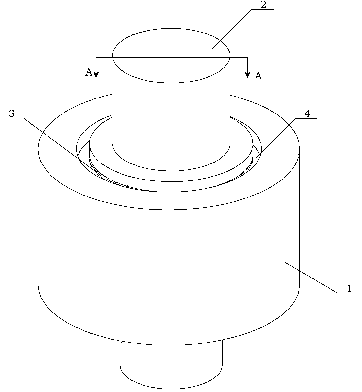
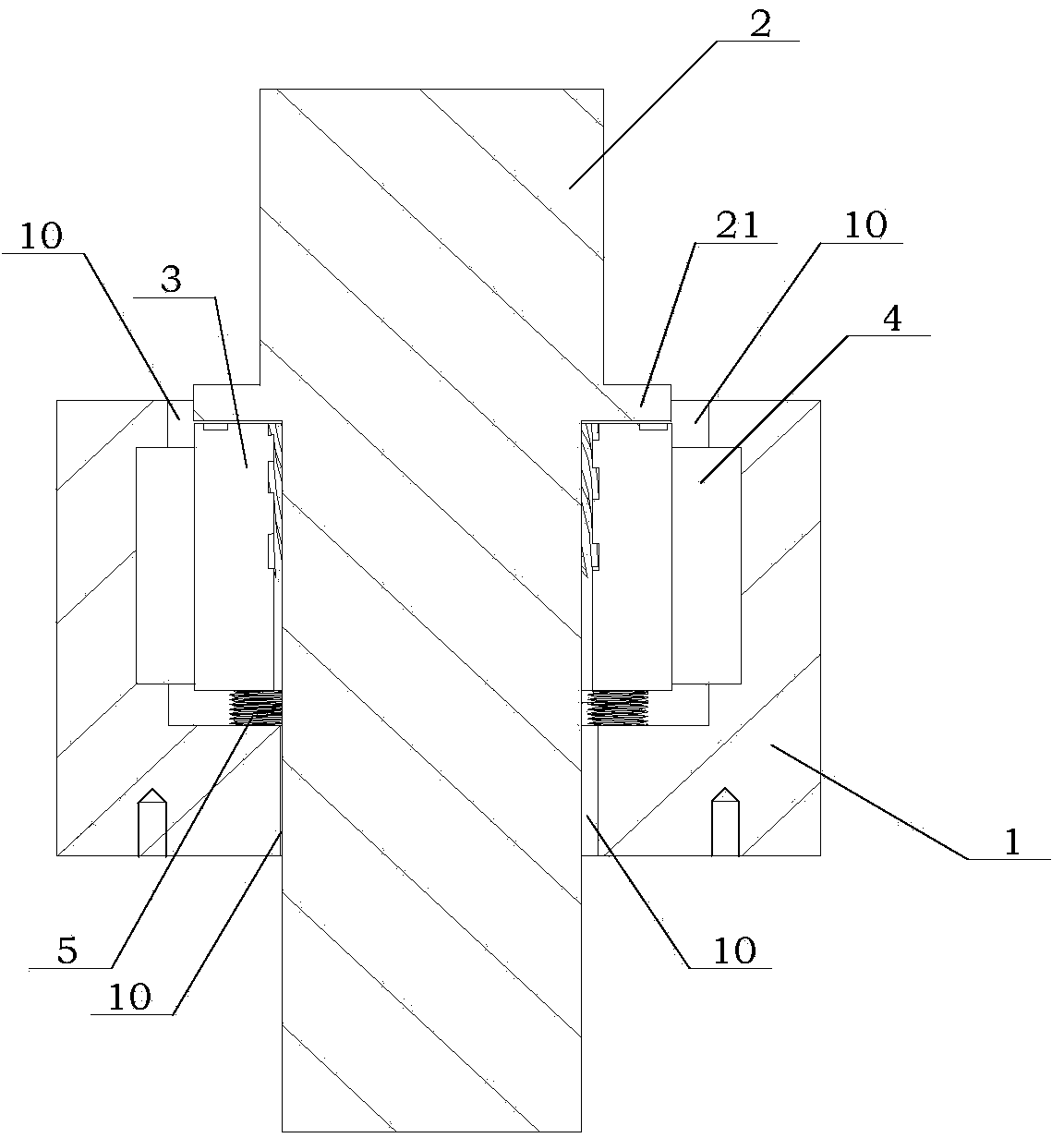
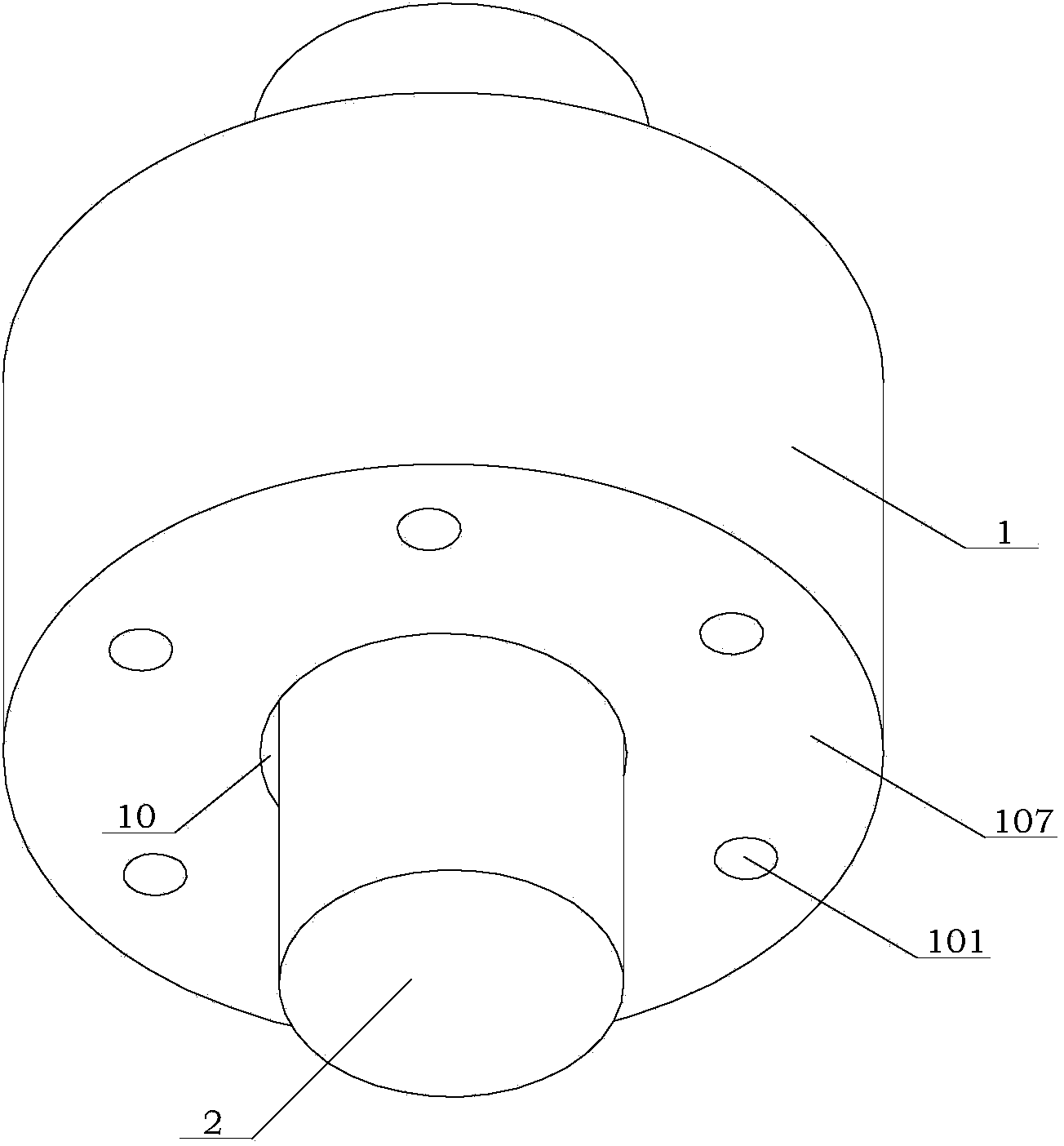
[0041] See figure 1 , Figure 1A , Figure 1B , Figure 1C As shown, the present invention is a gas-end cylindrical combined sealing device with spiral grooves. The sealing device includes a base 1, an end cylindrical floating seal ring 3, a cylindrical elastic support ring 4, and an end elastic support. 5; The end cylindrical floating seal ring 3 is installed with the rotating shaft of the existing high-speed rotating machinery, that is, the rotor journal 2; the end cylindrical floating seal ring 3 and the cylindrical surface are sequentially installed outside the rotor journal 2 After the elastic support ring 4 and the base 1 are formed, the gas-end cylindrical component sealing device with elastic support and spiral groove designed in the present invention is formed.

[0042] (1) Base 1

[0043] See figure 2 , Figure 2A As shown, the base 1 is an integrally fo...


PUM


Abstract

The invention discloses a gas end cylindrical surface combined sealing device provided with a spiral groove. The device comprises a base, an end cylindrical surface floating sealing ring, a cylindrical surface elastic support ring and an end face elastic support piece, wherein a rotor shaft neck in the conventional high-speed rotating machine is arranged in the end cylindrical surface floating sealing ring; after the end cylindrical surface floating sealing ring, the cylindrical surface elastic support ring and the base are arranged in sequence outside the rotor shaft neck, the gas end cylindrical surface combined sealing device provided with the spiral groove, designed by the invention is formed. A dynamic pressure cylindrical sealing area is formed between the cylindrical sealing interface of the end cylindrical surface floating sealing ring and the cylindrical surface of the rotor shaft neck. According to the gas end cylindrical surface combined sealing device disclosed by the invention, non-contact and small-leakage sealing is realized while adaptation to deformation in the working process of a working position is achieved via a flexible support and a dynamic pressure gas membrane; meanwhile, the requirement of mounting space for the non-shaft end position sealing is met through an end cylindrical surface structure.

Description

Technical field [0001] The invention belongs to the technical field of rotary shaft sealing, and particularly relates to a gas-end cylindrical combined sealing device with spiral grooves. This sealing device can be used in various forms of compressors, expanders, pumps and other high-speed rotating machinery. On the rotating shaft (that is, the rotor journal). Background technique [0002] Known high-speed fluid machinery has special working conditions at multiple sealing positions, contact seals are difficult to adapt to high slip speed and high ring temperature conditions, and fluid dynamic, static, and pressure combined end face gas sealing devices still have certain shortcomings. For example, due to the change in the working state of the rotor system, the adaptability of the seal position is insufficient when the seal position is deformed, and local contact occurs, resulting in increased leakage or contact wear, resulting in unstable seal performance; restricted by the struct...

Claims


Application Information

Patent Timeline
IPC IPC(8): F16J15/16
Inventor 马纲孙晓军罗先海
Owner BEIHANG UNIV
Learn More