Sliding type H-type piston coal gas tank and sliding type H-type piston thereof

A sliding type, gas tank technology, applied in the field of gas tank, can solve the problems of increasing the labor intensity of production units, increasing unsteady factors, and large piston steel consumption, reducing calculation height, reducing replacement time, and reducing steel consumption. Effect

Active Publication Date: 2014-03-12
CISDI ENG CO LTD
View PDF10 Cites 2 Cited by
  • Summary
  • Abstract
  • Description
  • Claims
  • Application Information

AI Technical Summary

Problems solved by technology

The traditional one-piece piston gas holder has several disadvantages. First, because the piston arches at the bottom of the piston cylinder, the action point of the gas is below, and the center of gravity of the piston is often higher than the action point of the gas. As a result, the gas holder is unstable, and when the piston is running quickly, it is easy to cause the piston to tilt
Second, because the piston T fence of the traditional one-piece piston gas holder needs to withstand external pressure (the working pressure of the gas holder), the traditional one-piece piston consumes a lot of steel
[0005] However, the fixed H-type piston gas holder also has several disadvantages. First, the dead space under the fixed arch. During the construction of the gas holder, due to the high height, the construction difficulty is increased and the construction cost is greatly increased. The second Second, the space under the fixed arch needs a lot of nitrogen to replace during the debugging and maintenance of the gas cabinet, and it also takes a lot of time to replace, which increases the labor intensity of the production unit and also increases the unstable factors

Method used


Image

  • Sliding type H-type piston coal gas tank and sliding type H-type piston thereof
  • Sliding type H-type piston coal gas tank and sliding type H-type piston thereof
  • Sliding type H-type piston coal gas tank and sliding type H-type piston thereof

Examples


Embodiment Construction

[0025] Hereinafter, preferred embodiments of the present invention will be described in detail with reference to the accompanying drawings. It should be understood that the preferred embodiments are only for illustrating the present invention, but not for limiting the protection scope of the present invention.

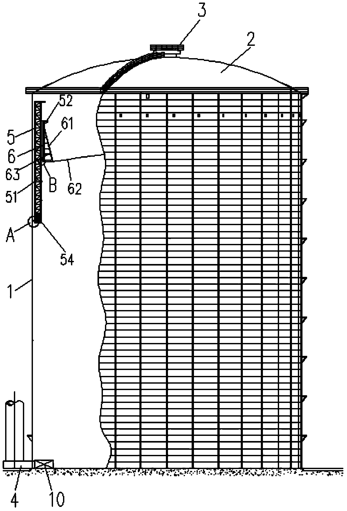
[0026] As shown in the figure, a sliding type H-type piston gas cabinet includes a gas cabinet cylinder 1, a roof plate 2 and a ventilation floor 3 are arranged on the top of the gas cabinet cylinder, and a gas tank is provided at the bottom of the gas cabinet cylinder. The inlet and outlet 4, the gas holder barrel is also provided with a sliding H-type piston 5 that can slide along its inner wall, and the sliding H-type piston includes a piston fence frame 51 that can slide along the inner wall of the gas holder barrel. The inner wall of the piston fence frame is provided with a sliding inner tank piston arch 6 that can slide along it, and the top of the piston fence ...


PUM


Abstract

The invention discloses a sliding type H-type piston coal gas tank and a sliding type H-type piston thereof. The sliding type H-type piston coal gas tank comprises a coal gas tank barrel, wherein a roof deck and a ventilation clerestory are arranged at the top of the coal gas tank barrel; a gas inlet is formed at the bottom of the coal gas tank barrel; the coal gas tank barrel is internally provided with a sliding type H-type piston which can slide along the inner wall; the sliding type H-type piston comprises a piston rail frame which can slide along the inner wall of the coal gas tank barrel; the inner wall of the piston rail frame is provided with a sliding type liner piston arch capable of sliding along the inner wall of the piston rail frame; the sliding type liner piston arch comprises a liner piston, a piston plate and a piston plate supporting truss; a rubber sealing film is arranged between the sliding type H-type piston and the inner wall of the coal gas tank barrel; and a liner rubber sealing film is also arranged between the sliding type liner piston arch and the inner wall of the piston rail frame. According to the sliding type H-type piston coal gas tank and the sliding type H-type piston thereof, an outer pressure calculation height of a piston cylinder can be reduced, the steel consumption amount of the piston is reduced, the displacement amount of nitrogen is reduced and the displacement time of the nitrogen is shortened.

Description

technical field [0001] The invention belongs to the field of gas cabinets, in particular to a sliding H-type piston gas cabinet and its piston. Background technique [0002] In the dry gas cabinet, there are mainly two types: one is a gas cabinet that uses thin lubricating oil as a sealing medium for sealing, and the other is a gas cabinet that uses a rubber membrane to seal. Among the thin oil seals, one is the metal sliding plate type Mann cabinet sealing device, and the other is a new type of rubber seal. Because the rubber seal of the new type of cabinet has the advantages of good sealing performance, the new type of cabinet is favored alone. However, the current thin oil sealed gas, the piston running speed is below 2.5m / min, which is affected by many factors, such as the manufacturing accuracy and installation accuracy of the gas holder cylinder; and how to maintain the height of the thin oil in the piston stably, etc. Etc., these factors have caused the difficulty th...

Claims


Application Information

Patent Timeline
Patent Type & Authority Applications(China)
IPC IPC(8): F17B1/24F17B1/02
Inventor 程杰李世鹏钱力刘超周伟彭放林刘奕寿贾艳艳黄丽文
Owner CISDI ENG CO LTD
Why Eureka
Try Eureka