Dew point dehumidifier
A dehumidifier and dew point technology, which is applied in the field of dehumidifiers for dehumidification by controlling the dew point, can solve the problems of complex dehumidifier system, inconvenient installation and use, and poor reliability, and achieve the effects of structural vibration reduction, simple structure, and reliable sealing
- Summary
- Abstract
- Description
- Claims
- Application Information
AI Technical Summary
Problems solved by technology
Method used
Image
Examples
Embodiment 1
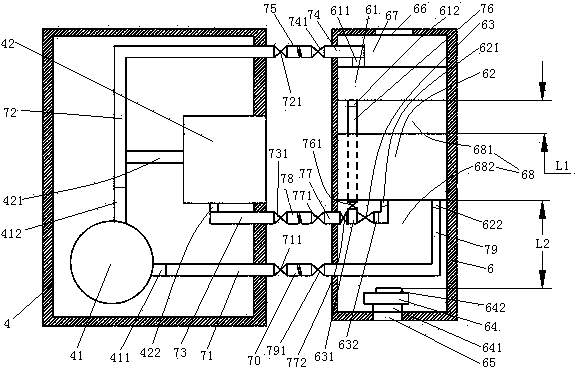
[0026] Embodiment one, see figure 1 , a dew point dehumidifier, including a refrigerant flow pipe, an outdoor casing 4 and an indoor casing 6.
[0027] There are 10 refrigerant circulation pipes. The seven refrigerant circulation pipes are the first refrigerant circulation pipe 71, the second refrigerant circulation pipe 72, the third refrigerant circulation pipe 73, the fourth refrigerant circulation pipe 74, the fifth refrigerant circulation pipe 75, the sixth refrigerant circulation pipe 76, the The seventh refrigerant circulation pipe 77 , the eighth refrigerant circulation pipe 78 , the ninth refrigerant circulation pipe 79 and the tenth refrigerant circulation pipe 70 .
[0028] A compressor 41 and a condenser 42 are arranged inside the outdoor cabinet 4 . The compressor 41 is an inverter compressor. The inlet 411 of the compressor leads out of the outdoor casing 4 through the first refrigerant circulation pipe 71 . The first refrigerant flow pipe 71 is provided with...
Embodiment 2
[0032] Embodiment two, the difference with embodiment one is:
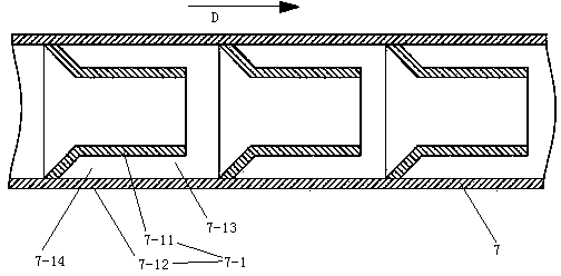
[0033] see figure 2 , The condensing flow pipe 7 is provided with a thermal insulation section 7-1. The heat insulation section 7-1 on a condensing flow pipe 7 can be designed in multiple sections and distributed along the length direction of the condensing flow pipe. This is the way in this embodiment. The advantage of this way is that it can quickly form a vacuum load. Pressure, so that it has a good heat insulation effect when it is frequently started and stopped; it does not need to be customized according to the length of the connecting pipe, it can be used as a general-purpose long pipe, and the corresponding length can be cut according to needs. Certainly the heat insulation section 7-1 on a condensing flow pipe 7 also can be designed as only one section, makes its length and the length of condensing flow pipe suitable. Heat insulation section The heat insulation section 7-1 includes an inner pipe 7-11 a...
Embodiment 3
[0044] Embodiment three, see Figure 7 , The difference with the second embodiment is: the two ends of the upper deformation channel 85 and the lower deformation channel 87 are provided with end caps 80, so that the upper deformation channel 85 and the lower deformation channel 87 form a closed cavity. The upper inclined support plate between the adjacent upper deformation channels 85 in the upper inclined support plate 84, the lower inclined support plate between the adjacent lower deformation channels 87 in the lower inclined support plate 86, and the middle base plate 82 are located on the corresponding A damping channel 88 is provided at the position between the adjacent upper deformation channel and the lower deformation channel. Both the upper deformation channel 85 and the lower deformation channel 87 are filled with damping fluid (the damping fluid is not shown in the figure). The upper deformation channel 85 and the lower deformation channel 87 are provided with an e...
PUM
 Abstract
Description
Claims
Application Information
 - R&D
- Intellectual Property
- Life Sciences
- Materials
- Tech Scout
- Unparalleled Data Quality
- Higher Quality Content
- 60% Fewer Hallucinations
Browse by: Latest US Patents, China's latest patents, Technical Efficacy Thesaurus, Application Domain, Technology Topic, Popular Technical Reports.
© 2025 PatSnap. All rights reserved.Legal|Privacy policy|Modern Slavery Act Transparency Statement|Sitemap|About US| Contact US: help@patsnap.com


