Ground source heat pump drying device

A drying device and ground source heat pump technology, applied in the direction of drying gas arrangement, heat pump, drying, etc., can solve the problems of conflicting energy policies, multiple energy sources, increasing the cost of mechanical drying, etc., and achieve the effect of less energy consumption

Inactive Publication Date: 2014-03-12
王震
View PDF0 Cites 2 Cited by
  • Summary
  • Abstract
  • Description
  • Claims
  • Application Information

AI Technical Summary

Problems solved by technology

Its disadvantage is that the drying device consumes more energy during drying, which not only increases the co...

Method used


Image

  • Ground source heat pump drying device
  • Ground source heat pump drying device

Examples


Embodiment 1

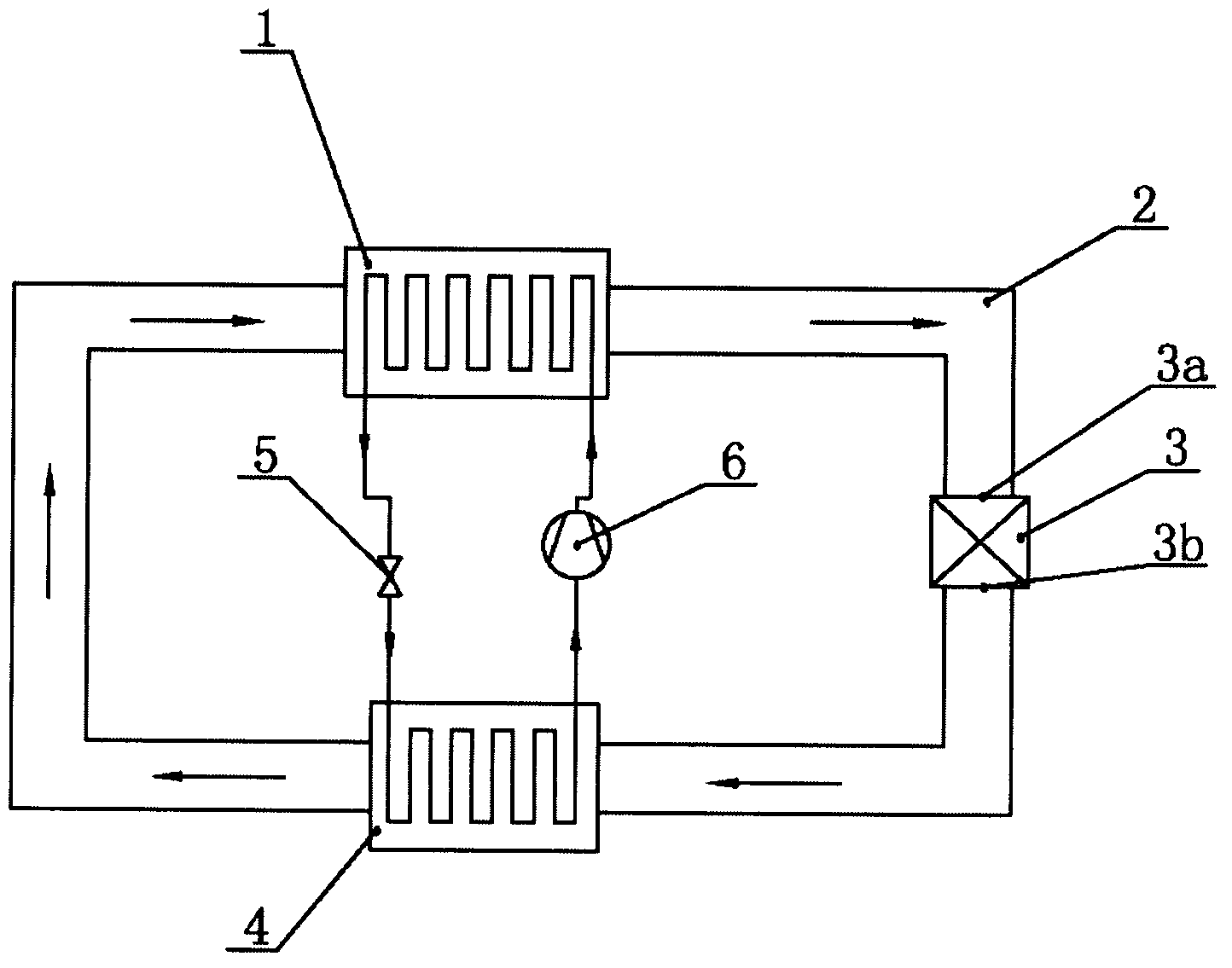
[0010] Such as figure 1 As shown, a ground source heat pump drying device includes a condenser 1 and an evaporator 4, a compressor 6 is arranged in series between the output end of the evaporator 4 and the input end of the condenser 1, and the output end of the condenser 1 is connected to the evaporator A throttling valve 5 is arranged in series between the input ends of the condensers 4, a loop pipe 2 passing through the condenser 1 and the evaporator 4 is arranged inside the condenser 1 and the evaporator 4, and a drier 3 is arranged on the loop pipe 2, The air discharge port 3b of the dryer 3 is connected to the evaporator 4, and the air inlet port 3a of the dryer 3 is connected to the condenser 1.

[0011] When the present invention works, the working medium stored in the heat pump system first absorbs the heat of the waste gas discharged from the air discharge end 3b of the drier 3 in the evaporator 4, is vaporized and becomes steam, and then enters the condenser through ...

Embodiment 2

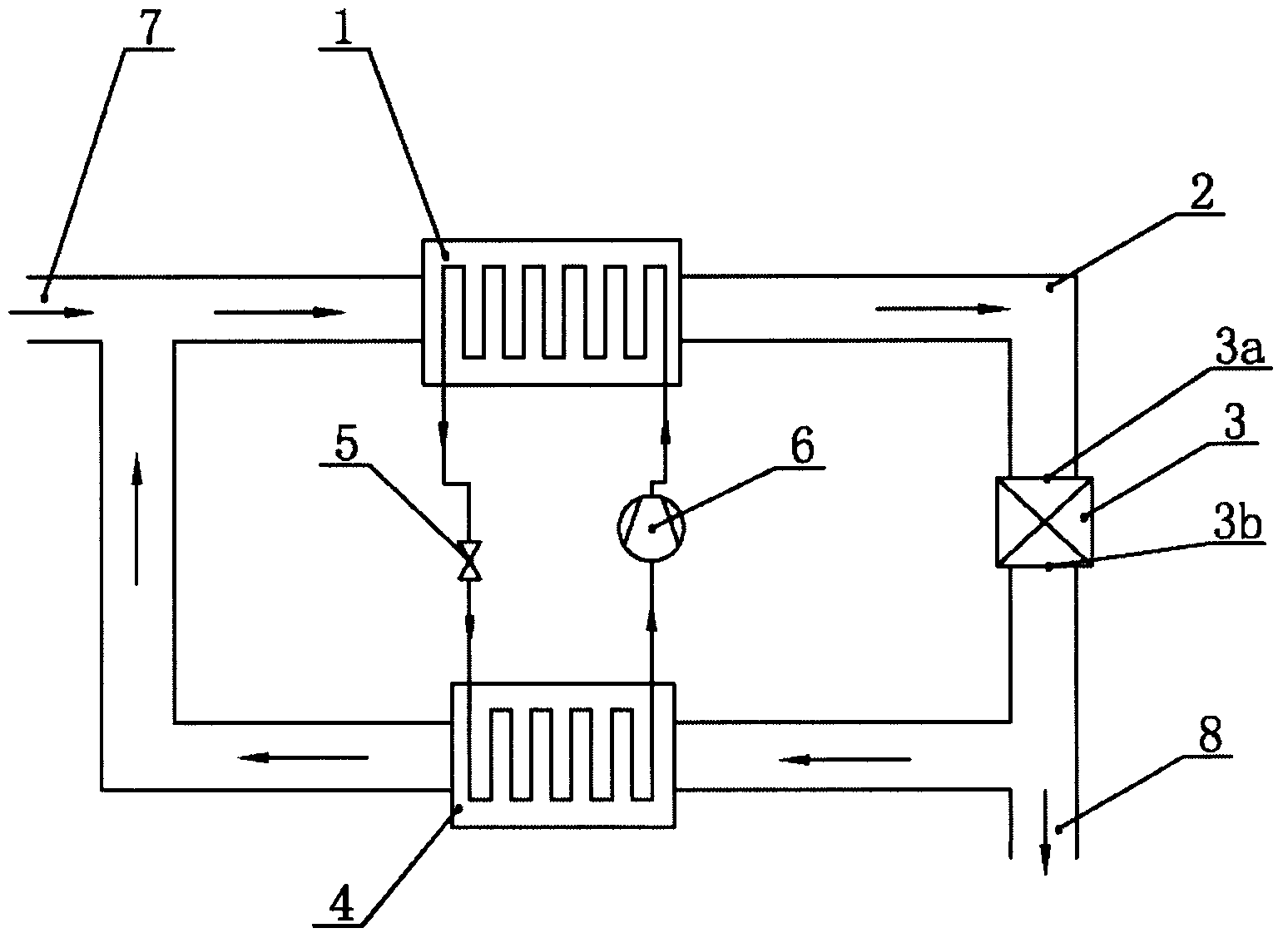
[0013] Such as figure 2 As shown, a ground source heat pump drying device includes a condenser 1 and an evaporator 4, a compressor 6 is arranged in series between the output end of the evaporator 4 and the input end of the condenser 1, and the output end of the condenser 1 is connected to the evaporator A throttling valve 5 is arranged in series between the input ends of the condensers 4, a loop pipe 2 passing through the condenser 1 and the evaporator 4 is arranged inside the condenser 1 and the evaporator 4, and a drier 3 is arranged on the loop pipe 2, The air discharge end 3b of the drier 3 is connected to the evaporator 4, the air inlet end 3a of the drier 3 is connected to the condenser 1, and an air inlet 7 is arranged on a section of the loop pipeline 2 far away from the drier 3, and an air inlet 7 is arranged on the loop pipeline. An air outlet 8 is provided on a section of pipeline between the dryer 3 and the evaporator 4 .

[0014] When the present invention works...


PUM


Abstract

The invention discloses a ground source heat pump drying device and belongs to the field of drying devices. The ground source heat pump drying device comprises an evaporator. The output end of the evaporator is connected with the input end of a compressor. The output end of the compressor is connected with the input end of a condenser. The output end of the condenser is connected with the input end of a throttle valve. The output end of the throttle valve is connected with the input end of the evaporator. Loop channels which are communicated are arranged in the condenser and the evaporator respectively in a penetrating mode. Driers are arranged on the loop channels. Air discharging ends of the driers are connected with the input end of the evaporator. Air inlet ends of the driers are connected with the output end of the condenser. The ground source heat pump drying device solves the problem that energy loss is high in the drying process in the prior art, energy loss is low in the drying process, and the device accords with the energy policy of global energy conservation and emission reduction. The device is suitable for drying various kinds of rice.

Description

technical field [0001] The invention relates to a drying device, in particular to a ground source heat pump drying device. Background technique [0002] China's rice output ranks first in the world, with an annual total output of about 190 million tons, accounting for about 40% of the world's total output. With the development of agricultural mechanization in our country, the application of rice drying mechanization is gradually increasing. In the prior art, there is a paddy drying machine whose publication number is: CN2446475, which includes a material barrel, a chassis and a blanking barrel. A fan is installed in the chassis and an air inlet is provided. The chassis and the barrel are connected through a hot air pipe. , the outlet of the hot air pipe is equipped with a high-temperature resistance wire heater, and a thyristor temperature switch is installed on the chassis to adjust the heater. The lower part is the blanking barrel. The disadvantage is that the drying de...

Claims


Application Information

Patent Timeline
IPC IPC(8): F26B21/02F25B30/06
Inventor 王震
Owner 王震
Why Eureka
Try Eureka