Multielement linear array high-speed heat distribution imaging detector
An imaging detector and heat distribution technology, applied in electric radiation detectors, radiation pyrometry, instruments, etc., can solve the problems of limited single-probe detection parts, high price, complex multi-probe technology, etc., and achieve pyroelectric effect time Small constant, wide field of view, and high light-gathering efficiency
- Summary
- Abstract
- Description
- Claims
- Application Information
AI Technical Summary
Problems solved by technology
Method used
Image
Examples
specific Embodiment approach 1
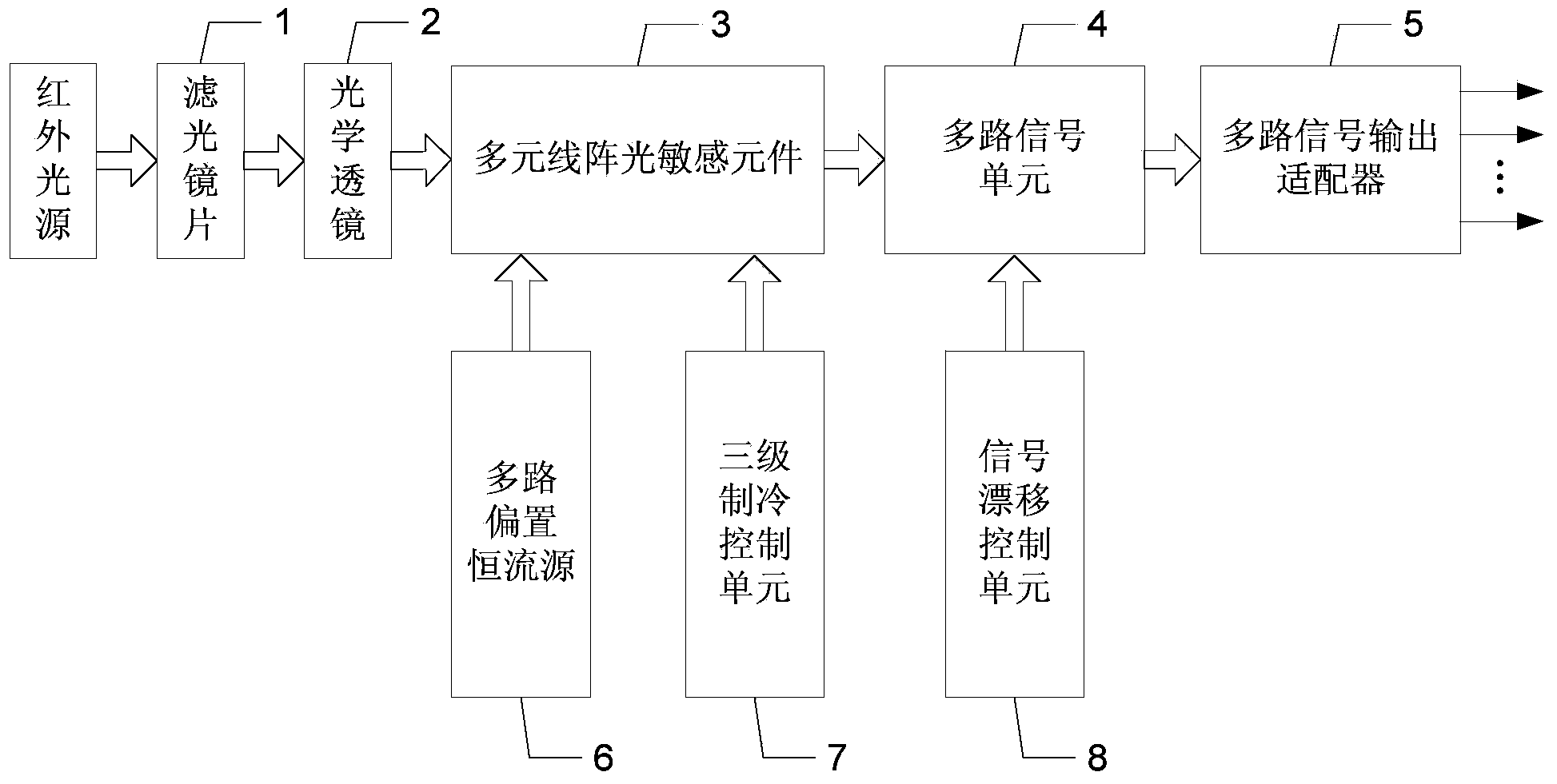
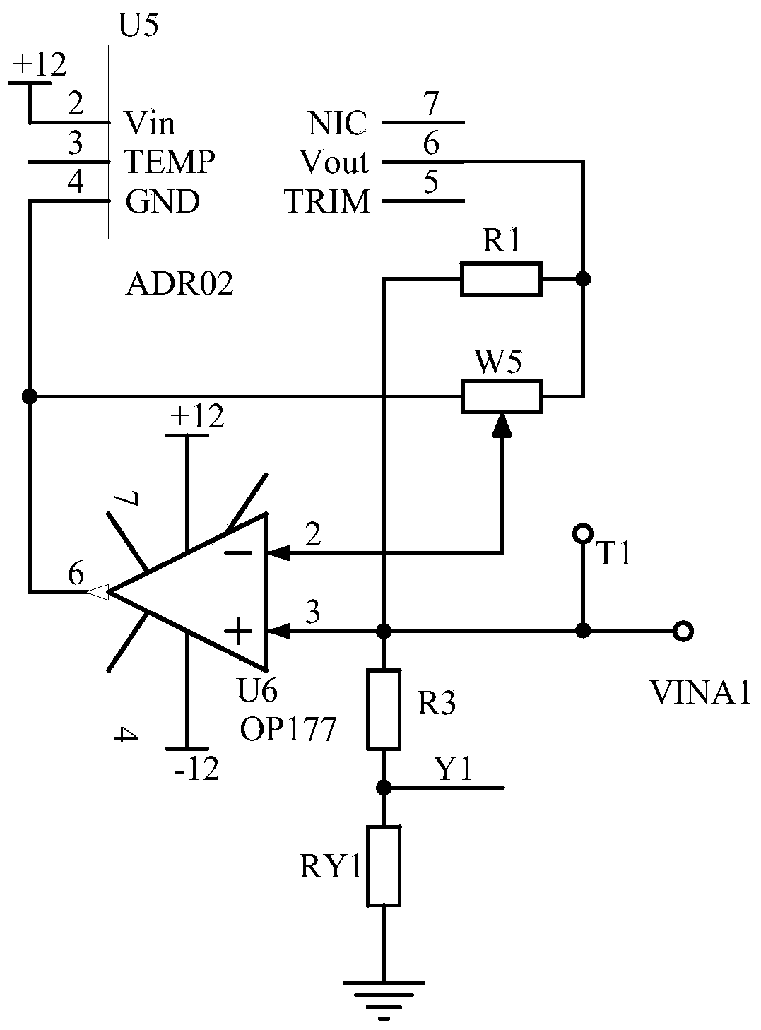
[0019] Specific implementation mode one: the following combination Figure 1 to Figure 3 Describe this embodiment, the multi-element linear array high-speed thermal distribution imaging detector described in this embodiment includes a filter lens 1, an optical lens 2, a multi-element linear array photosensitive element 3, a multi-channel signal amplification unit 4, and a multi-channel signal output Adapter 5, multi-channel bias constant current source 6, three-stage refrigeration control unit 7 and signal drift control unit 8;
[0020] The high-speed moving object to be measured reflects the mixed beam of visible light and infrared light;
[0021] After the mixed beam of visible light and infrared light is filtered out by the filter lens 1 to filter out the visible light, the output infrared beam is incident on the photosensitive surface of the multi-element linear array photosensitive element 3 through the optical lens 2;
[0022] The electrical signal output end of the mul...
specific Embodiment approach 2
[0030] Specific embodiment two: this embodiment will further explain embodiment one, the optical filter lens 1 is a visible light bandpass filter zinc sulfide lens, the optical lens 2 is a wide-field double-spherical infrared harmonic diffraction lens, and the mixed beam of visible light and infrared light is incident To the visible light band-pass filter zinc sulfide lens, the visible light band-pass filter zinc sulfide lens outputs infrared beams, and enters the wide-field double-spherical infrared harmonic diffraction lens, and the wide-field double-spherical infrared harmonic diffraction lens outputs the surface of the high-speed moving object to be measured The temperature image is focused on the photosensitive surface of the multi-element linear array photosensitive element 3 .
[0031] The high-speed moving object to be tested is easy to generate heat. The higher the temperature of the high-speed moving object to be measured, the stronger the intensity of the infrared li...
specific Embodiment approach 3
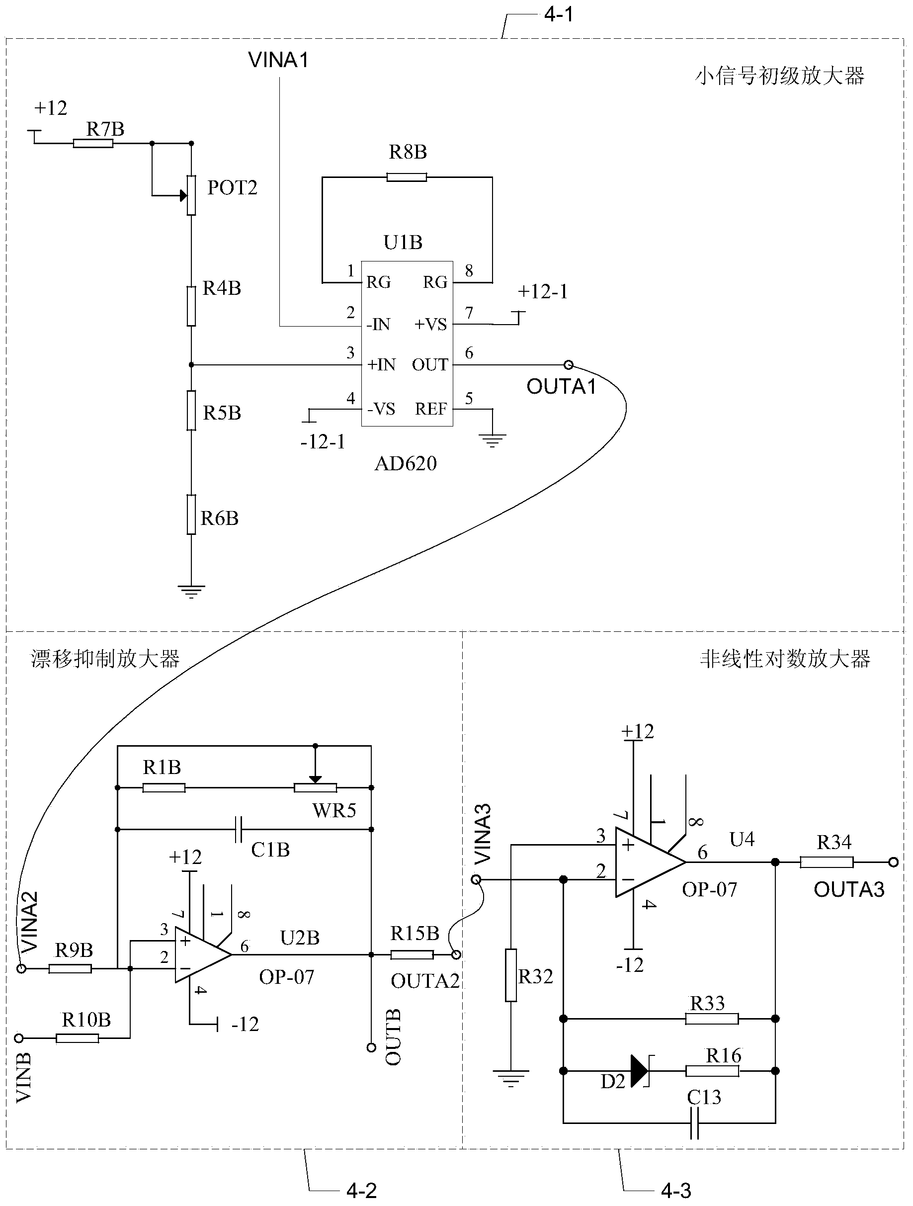
[0033] Specific implementation mode three: the following combination figure 2 and Figure 5 Describe this embodiment mode, this embodiment mode will further illustrate Embodiment 1, multi-channel signal amplifying unit 4 comprises small-signal primary amplifier 4-1, drift suppressing amplifier 4-2 and nonlinear logarithmic amplifier 4-3, small-signal primary amplifier The output terminal of 4-1 is connected with the input terminal of drift suppression amplifier 4-2, and the output terminal of drift suppression amplifier 4-2 is connected with the input terminal of nonlinear logarithmic amplifier 4-3.
[0034] Small-signal primary amplifier 4-1 adopts AD620 operational amplifier as the core chip.
[0035] The output terminal OUTA3 of the nonlinear logarithmic amplifier 4-3 is used as the signal output of the detector, and is connected to the host computer for signal acquisition.
[0036] The multi-channel signal amplifying unit 4 amplifies the output signal of the multi-eleme...
PUM
 Abstract
Description
Claims
Application Information
 - R&D
- Intellectual Property
- Life Sciences
- Materials
- Tech Scout
- Unparalleled Data Quality
- Higher Quality Content
- 60% Fewer Hallucinations
Browse by: Latest US Patents, China's latest patents, Technical Efficacy Thesaurus, Application Domain, Technology Topic, Popular Technical Reports.
© 2025 PatSnap. All rights reserved.Legal|Privacy policy|Modern Slavery Act Transparency Statement|Sitemap|About US| Contact US: help@patsnap.com


