Improved Z-source boosting DC (direct current)-DC converter

A DC-DC, improved technology, applied in the direction of converting DC power input to DC power output, instruments, adjusting electrical variables, etc., can solve the problems of large starting inrush current and voltage, limit circuit application, etc. The effect of good starting inrush current and voltage and low capacitor voltage stress

Inactive Publication Date: 2014-03-12
SOUTH CHINA UNIV OF TECH
View PDF4 Cites 17 Cited by
  • Summary
  • Abstract
  • Description
  • Claims
  • Application Information

AI Technical Summary

Problems solved by technology

The Z-source step-up DC-DC converter proposed in recent years is a high-gain DC-DC converter, but the circuit has a high Z-source impedance network capa

Method used


Image

  • Improved Z-source boosting DC (direct current)-DC converter
  • Improved Z-source boosting DC (direct current)-DC converter
  • Improved Z-source boosting DC (direct current)-DC converter

Examples


Embodiment

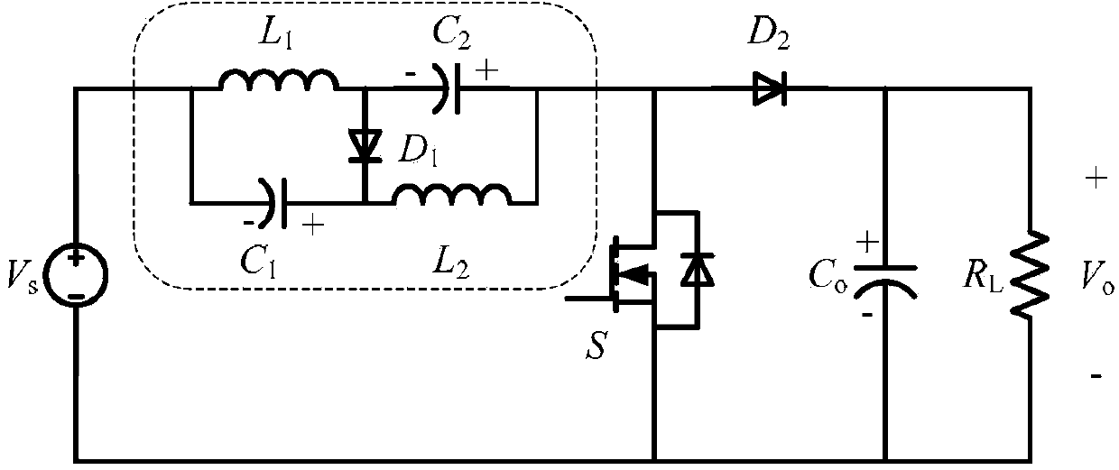
[0018] Such as figure 1 As shown, an improved Z-source step-up DC-DC converter, including the voltage source V s , Z source impedance network, MOS tube S, second diode D 2 , output filter capacitor C o and load R L ; The voltage source V s , Z source impedance network and MOS transistor S form a boost circuit, the second diode D 2 , output filter capacitor C o and load R L constitute the output circuit.

[0019] The Z source impedance network consists of a first inductor L 1 , the second inductance L 2 , the first capacitance C 1 , the second capacitance C 2 and the first diode D 1 constitute;

[0020] The specific connection method of the circuit is:

[0021] The voltage source V s The positive pole of the first inductor L 1 One end and the first capacitor C 1 connected to the cathode of the first diode D 1 The anodes are respectively connected with the first inductor L 1 the other end and the second capacitor C 2 The cathode connection; the first diode D ...


PUM


Abstract

The invention discloses an improved Z-source boosting DC (direct current)-DC converter, comprising a voltage source, a Z-source impedance network, an MOS (metal oxide semiconductor) tube, a second diode, an output filter capacitor and a load; the Z-source impedance network is formed by a first inductor, a second inductor, a first capacitor, a second capacitor and a first diode. The voltage source Vs, the Z-source impedance network and the MOS tube form a boosting circuit; the second diode, the output filter capacitor and the load form an output circuit. The improved Z-source boosting DC-DC converter is simple in integral circuit structure and has higher output voltage gain, the capacitance and voltage stress of the Z-source impedance network is low, and the circuit has no starting impact problem.

Description

technical field [0001] The invention relates to the field of power electronics, in particular to an improved Z-source step-up DC-DC converter. Background technique [0002] In fuel cell power generation and photovoltaic power generation, due to the low DC voltage provided by a single solar cell or a single fuel cell, it cannot meet the electricity demand of existing electrical equipment, nor can it meet the needs of grid connection. It is often necessary to combine multiple batteries connected in series to achieve the desired voltage. On the one hand, this method greatly reduces the reliability of the entire system, and on the other hand, it needs to solve the problem of series voltage equalization. For this reason, a high-gain DC-DC converter capable of converting low voltage to high voltage is required. The Z-source step-up DC-DC converter proposed in recent years is a high-gain DC-DC converter, but the circuit has a high Z-source impedance network capacitor voltage stre...

Claims


Application Information

Patent Timeline
IPC IPC(8): H02M3/155H02M1/32
Inventor 丘东元杨立强张波张桂东黄子田
Owner SOUTH CHINA UNIV OF TECH
Why Eureka
Try Eureka