
Clock synchronization control method and system and positron emission tomography scanner

A clock synchronization and control system technology, applied in the field of nuclear medicine imaging, can solve the problems of transmission distance limitation, increase system cost and complexity, increase the difficulty of system wiring, etc., and achieve the effect of streamlining the system structure

Inactive Publication Date: 2014-03-12
INST OF HIGH ENERGY PHYSICS CHINESE ACADEMY OF SCI
View PDF3 Cites 13 Cited by
  • Summary
  • Abstract
  • Description
  • Claims
  • Application Information

AI Technical Summary

Problems solved by technology

However, this prior art needs to design an independent global clock board for the PET electronics system, thus increasing the system cost and complexity, and the global clock board and other boards are connected by ordinary twisted-pair wires, and the transmission distance There are some restrictions, which increase the difficulty of system wiring

Method used


Image

  • Clock synchronization control method and system and positron emission tomography scanner
  • Clock synchronization control method and system and positron emission tomography scanner
  • Clock synchronization control method and system and positron emission tomography scanner

Examples


Embodiment Construction

[0024] In order to make the purpose, technical solutions and advantages of the embodiments of the present invention clearer, the technical solutions in the embodiments of the present invention will be clearly and completely described below in conjunction with the drawings in the embodiments of the present invention. Obviously, the described embodiments It is a part of embodiments of the present invention, but not all embodiments. Elements and features described in one drawing or one embodiment of the present invention may be combined with elements and features shown in one or more other drawings or embodiments. It should be noted that representation and description of components and processes that are not related to the present invention and known to those of ordinary skill in the art are omitted from the drawings and descriptions for the purpose of clarity. Based on the embodiments of the present invention, all other embodiments obtained by persons of ordinary skill in the ar...


PUM


Abstract

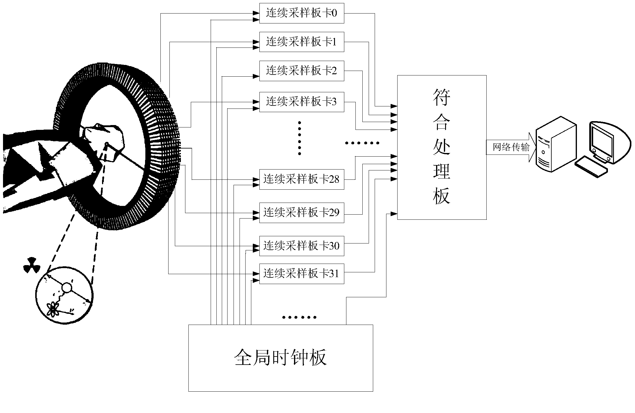
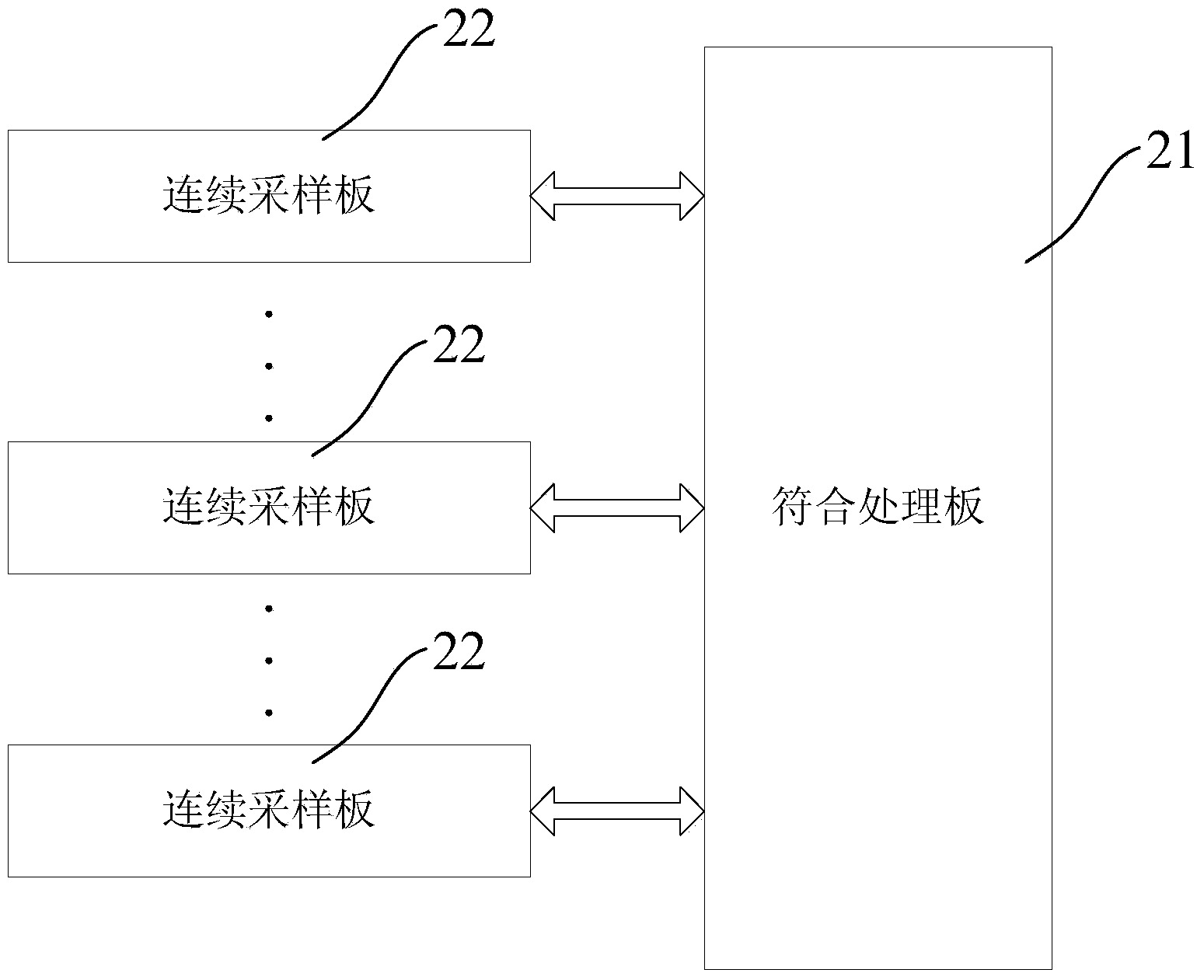
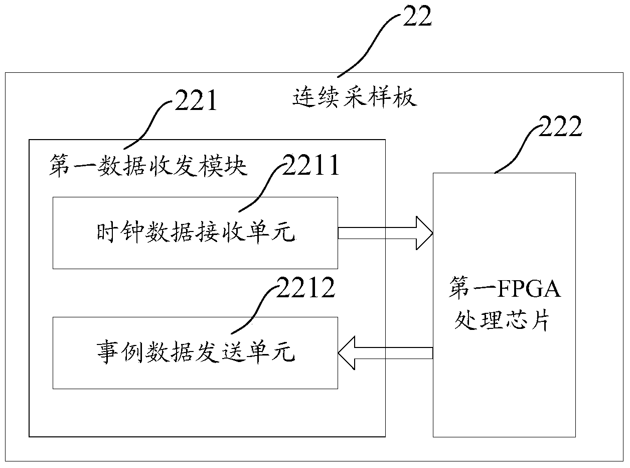
The invention relates to a clock synchronization control method, a clock synchronization control system and a positron emission tomography scanner. The clock synchronization control system comprises a coincidence processing module CPM and a plurality of continuous sampling modules CSM respectively connected with the coincidence processing module, wherein the coincidence processing module is used for fanning local crystal oscillators, as source clocks, out through multiple routes, correspondingly sending multiple routes of fan-out clock data to each continuous sampling module and receiving, judging and selecting example data sent by each continuous sampling module; each continuous sampling module is used for receiving the multiple routes of clock data sent by the coincidence processing module, recovering the source clocks according to the received clock data, taking the recovered clock as main working clock sampling example data and sending the collected example data to the coincidence processing module. According to the clock synchronization control system, bidirectional data transmission is realized between the continuous sampling modules and the coincidence processing module, a global clock module does not need to be singly arranged, and the global clock distribution of each continuous sampling module is realized through the coincidence processing module, so that the system structure is simplified.

Description

technical field [0001] The invention relates to the field of nuclear medical imaging, in particular to a clock synchronization control method and system, and a positron emission tomography scanner. Background technique [0002] The main purpose of Positron Emission Tomography (PET) is to image and determine the position of the emitting positron nuclide, so as to obtain the distribution of tracer drugs in the body, so as to diagnose tumors and other diseases the goal of. Generally speaking, the entire PET equipment can be divided into three parts: the detector subsystem, the electronics subsystem and the image reconstruction subsystem. Among them, the detector system mainly detects the gamma photons generated by the annihilation of positive and negative electrons, and converts the optical signal into an electrical signal through a photomultiplier tube (Photo Multiplier Tube, PMT for short), and then completes the preamplification and signal preamplification through front-end...

Claims


Application Information

Patent Timeline
IPC IPC(8): H04L7/00A61B6/03
Inventor 丰宝桐王培林孙芸华周魏魏龙
Owner INST OF HIGH ENERGY PHYSICS CHINESE ACADEMY OF SCI
Learn More